
Method for separating substrates

a substrate and laser-assisted technology, applied in the direction of glass making apparatus, manufacturing tools, welding/soldering/cutting articles, etc., can solve the problems of complex post-processing, insufficient quality of edges, and low cost efficiency, so as to reduce the power of lasers and reduce the use of lasers. , the effect of high edge quality and high and defined edge quality

Active Publication Date: 2019-10-24
SCHOTT AG
View PDF0 Cites 4 Cited by
  • Summary
  • Abstract
  • Description
  • Claims
  • Application Information

AI Technical Summary

Benefits of technology

This patent describes a method for improving the quality of separation edges in a substrate. The method involves using a laser to create filamentary defects along a predetermined separation line, resulting in a high quality edge that does not require additional sanding. The laser pulses create linear defects that precisely match the desired separation line. By increasing the spacing between the defects, the method achieves smoother edges and faster cutting speeds. Overall, this technique is a precise and efficient way to separate sheets of materials with high-quality edges.

Problems solved by technology

The method is cost-effective, but is essentially limited to straight cuts.
After the breaking, the edges often do not have a sufficient quality, so that complex post-processing might be necessary, e.g. by grinding or polishing.
Another method is water-jet cutting, which allows free-form geometries but is rather slow and expensive, at the same time with limited quality, so that further post-processing of the edge is typically necessary with this process as well.
However, the laser scribing is not suitable, or only at a high loss of quality, for glasses having a greater thickness, and especially not for glasses having a low coefficient of thermal expansion.
However, during the cleavage step, in particular in the case of complex geometries or materials with a low coefficient of thermal expansion, errors may occur, for example in that the crack does not follow the preliminarily introduced separation line and runs away, or in that the crack does not start or stops.
It has been found that such issues may present itself in different ways for different glasses, i.e. sometimes will also depend on the glass to be separated.
In other words, large spacings between the defects result in smoother edges.

Method used


Image

  • Method for separating substrates
  • Method for separating substrates
  • Method for separating substrates

Examples


Embodiment Construction

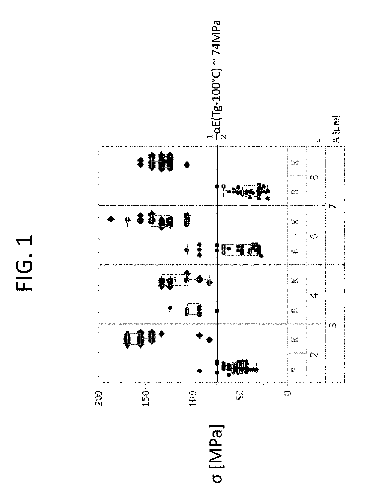
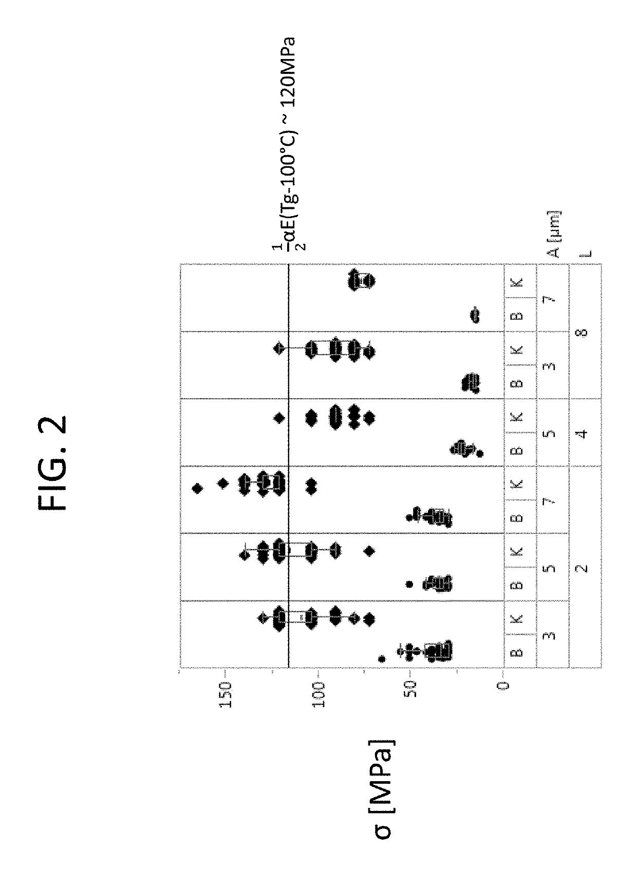
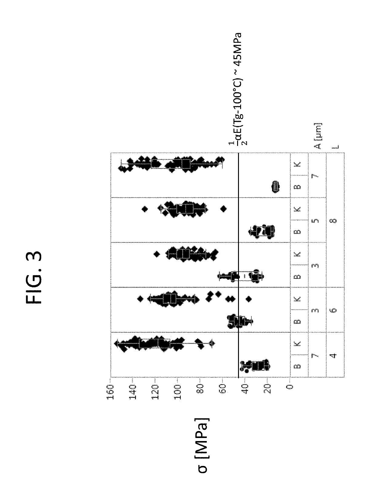
[0124]Referring to FIGS. 1 to 3, the results of a DOE series of tests are shown for three different glasses, namely SCHOTT AF32® (FIG. 1), SCHOTT D263® (FIG. 2), and SCHOTT BOROFLOAT® 33 (FIG. 3).

[0125]This represents a selection of examples. More generally, the invention can be used for various substrates, in particular made of glass, glass ceramics, and / or silicon with filamentation, in particular even for materials having a low coefficient of thermal expansion.

[0126]Filamentation was performed for each of a plurality of samples of these glasses, i.e. spaced apart defects were introduced into the volume of the respective sample along a separation line by laser pulses of a laser.

[0127]For the samples made of SCHOTT AF32® or SCHOTT D263®, substrate thicknesses of approximately 100 μm were in particular selected, and for the samples made of SCHOTT BOROFLOAT® 33, substrate thicknesses of approximately 1 mm were in particular selected.

[0128]After filamentation, the breaking strength σB...


PUM

PropertyMeasurementUnit
Temperatureaaaaaaaaaa

Abstract

A method for separating a substrate of a brittle-hard material is provided. The method includes the steps of introducing defects into the substrate at a spacing from one another along a separation line using at least one pulsed laser beam; selecting an average spacing between neighboring defects and a number of laser pulses for generating a respective defect such that a breaking stress (σB) for separating the substrate along the separation line is smaller than a first reference stress (σR1) of the substrate and such that an edge strength σK of the separation edge obtained after separation is greater than a second reference stress (σR2) of the substrate; and separating the substrate after introducing the defects by applying a stress along the separation line.

Description

CROSS REFERENCE TO RELATED APPLICATIONS[0001]This application is a continuation of International Application PCT / EP2017 / 084177 filed Dec. 21, 2017, which claims benefit under 35 USC § 119 of German Application 10 2017 100 015.1 filed Jan. 2, 2017, the entire contents of both of which are incorporated herein by reference.BACKGROUND1. Field of the Invention[0002]The invention relates to a method for laser-assisted separation of substrates, in particular substrates made of glass, glass ceramics, or silicon, in which defects are introduced into the substrate at a spacing from one another along a predetermined separation line using a pulsed laser beam. The invention furthermore relates to a workpiece, in particular a glass product, a glass ceramic product, and / or a silicon product, which includes defects that are spaced-apart along a separation line.2. Description of Related Art[0003]One cutting method widely used in glass industry is mechanical scribing and breaking. The method is cost-...

Claims


Application Information

Patent Timeline
IPC IPC(8): C03B33/02B23K26/53B23K26/00
CPCC03B33/0222B23K26/0006B23K26/53B23K2103/54Y02P40/57
Inventor WAGNER, FABIANPLAPPER, VOLKERORTNER, ANDREASSCHMITT, SIMONLENTES, FRANK-THOMASSEIDL, ALBRECHTMAKACS, ANTALBARTHOLOME, PATRICK
Owner SCHOTT AG
Learn More