Coil device and holder
- Summary
- Abstract
- Description
- Claims
- Application Information
AI Technical Summary
Benefits of technology
Problems solved by technology
Method used
Image

Examples
first embodiment
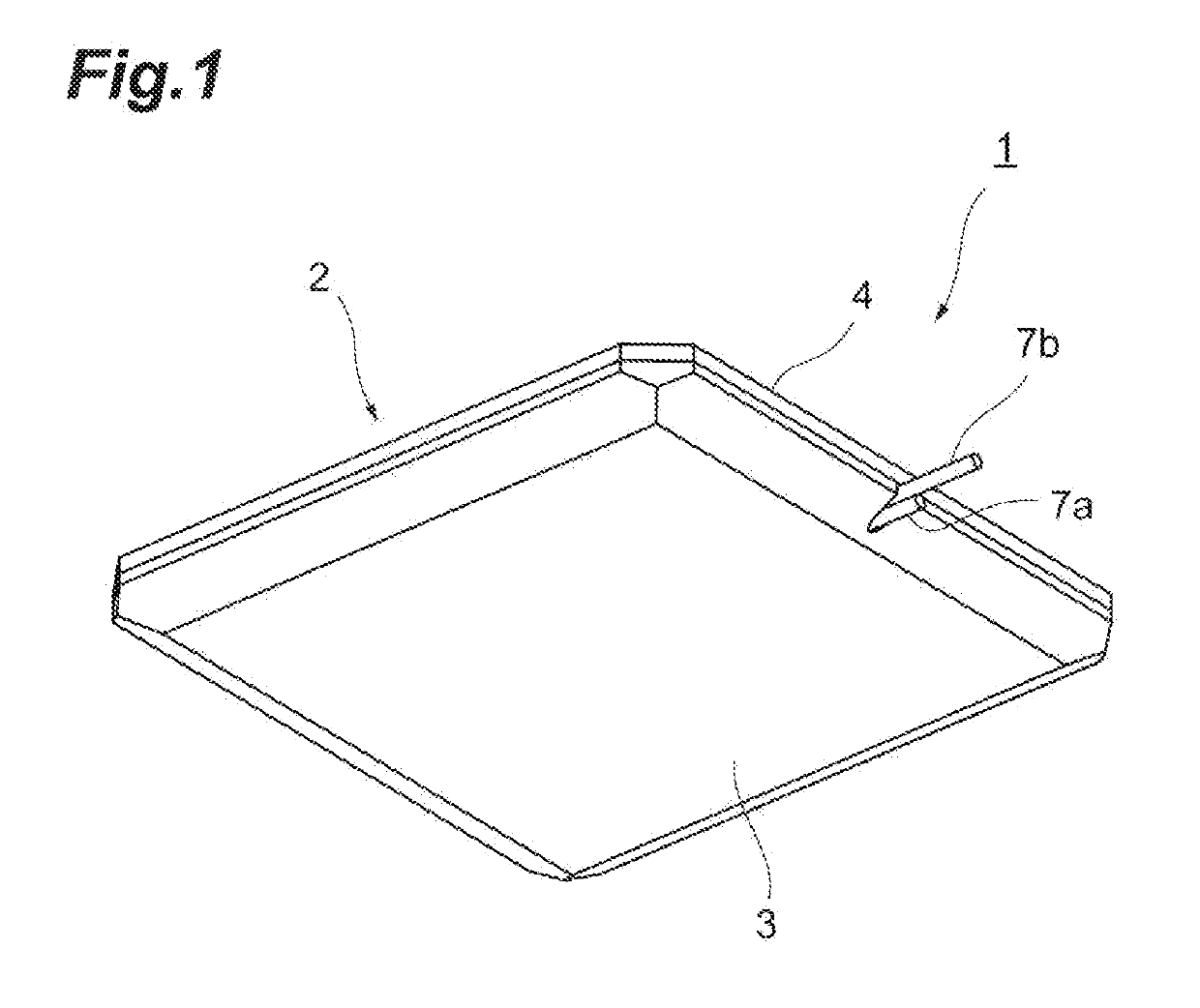
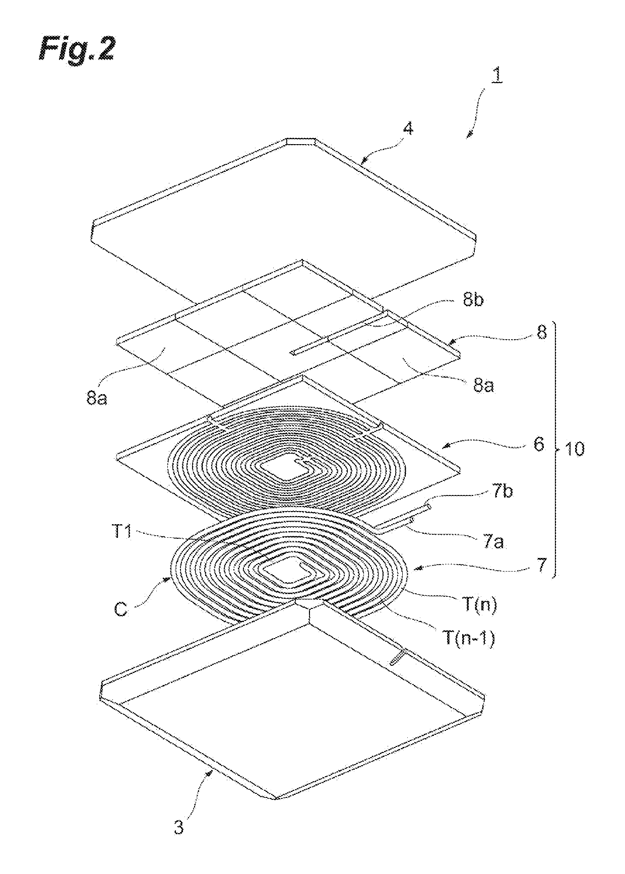
[0033]First, a coil device 1 will be described with reference to FIGS. 1 and 2. The coil device 1 is used in a power receiving device or a power transmitter in a wireless power transfer system. The wireless power transfer system is a system for charging a battery mounted in a vehicle such as an electric car and a hybrid car. The coil device 1 may be used for both the power receiving device and the power transmitter.
[0034]In a case where the coil device 1 is used in the power receiving device, the coil device 1 as a power receiving coil device is fixed to, for example, the chassis of the vehicle. The battery is connected to the coil device 1 via a power receiving circuit, a charging circuit, or the like. In a case where the coil device 1 is used in the power transmitter, the coil device 1 as a power transmission coil device is fixed to, for example, a road surface. An external power source is connected to the coil device 1 via a power transmission circuit, a rectifier circuit, or th...
second embodiment
[0071]A coil portion 10C of a coil device will be described below. As illustrated in FIGS. 9A and 9B, the coil portion 10C includes a shield plate (nonmagnetic member) 9C disposed on the back surface side of the bobbin 6. The shield plate 9C is made of an electrically conductive nonmagnetic material. The shield plate 9C is made of, for example, an aluminum plate or a copper plate. The shield plate 9C includes a fourth groove 14 on the back surface side of the shield plate 9C, and the fourth groove 14 is a fourth holding portion that holds the conductive wire 7. Provided on the back surface side of the shield plate 9C are a plurality of the fourth grooves 14 folded in a U shape and a plurality of connection grooves 24 connecting the plurality of fourth grooves 14. One of the fourth grooves 14 reaches a first side surface 9d, and another fourth groove 14 reaches the first side surface 9d at a position different from the fourth groove 14. In other words, the fourth groove 14 and the c...
third embodiment
[0075]A coil portion 10D of a coil device will be described below. As illustrated in FIGS. 11A and 11B, the coil portion 10D includes a shield plate (nonmagnetic member) 9D disposed on the back surface side of the bobbin 6. The shield plate 9D is made of an electrically conductive nonmagnetic material. The shield plate 9D is made of, for example, an aluminum plate or a copper plate. The shield plate 9D includes a fourth groove 34 on the back surface side of the shield plate 9D, and the fourth groove 34 is a fourth holding portion that holds the conductive wire 7. Provided on the back surface side of the shield plate 9D are a plurality of the loop-shaped fourth grooves 34 and a plurality of fifth grooves 15 connecting the plurality of fourth grooves 34 and the first side surface (peripheral edge portion) 9d. The plurality of fourth grooves 34 form a concentric circular shape. Two fifth grooves 15 intersect in a cross shape in the middle of the fourth groove 34. Each of the two fifth...
PUM
 Abstract
Description
Claims
Application Information
 - R&D
- Intellectual Property
- Life Sciences
- Materials
- Tech Scout
- Unparalleled Data Quality
- Higher Quality Content
- 60% Fewer Hallucinations
Browse by: Latest US Patents, China's latest patents, Technical Efficacy Thesaurus, Application Domain, Technology Topic, Popular Technical Reports.
© 2025 PatSnap. All rights reserved.Legal|Privacy policy|Modern Slavery Act Transparency Statement|Sitemap|About US| Contact US: help@patsnap.com