Ac/dc converters having power factor correction

Active Publication Date: 2019-10-24
SIGNIFY HLDG BV
View PDF2 Cites 1 Cited by
  • Summary
  • Abstract
  • Description
  • Claims
  • Application Information

AI Technical Summary

Benefits of technology

[0028]This circuit enables an increase in the power factor compared to a basic rectifier circuit, but without introducing excessive complexity to the circuit. This is achieved by setting the timing at which current is drawn from the input and provided to the output (i.e. the load) in dependence on the phase of the AC input signal. It enables integration of the converter into a low cost product, such as an LED bulb.
[0029]The current source circuit is for example adapted to deliver a constant current when switched on. This enables a simple implementation of the current source circuit.
[0030]In one example the current source circuit comprises a linear current source circuit. This enables a simple circuit implementation. The current source circuit for example comprises a transistor in series with the DC output and a constant voltage source provid

Problems solved by technology

The limitation of this circuit is that the power factor only reaches 0.5 to 0.6, and is therefore not suited to meet h

Method used


Image

  • Ac/dc converters having power factor correction
  • Ac/dc converters having power factor correction
  • Ac/dc converters having power factor correction

Examples


Embodiment Construction

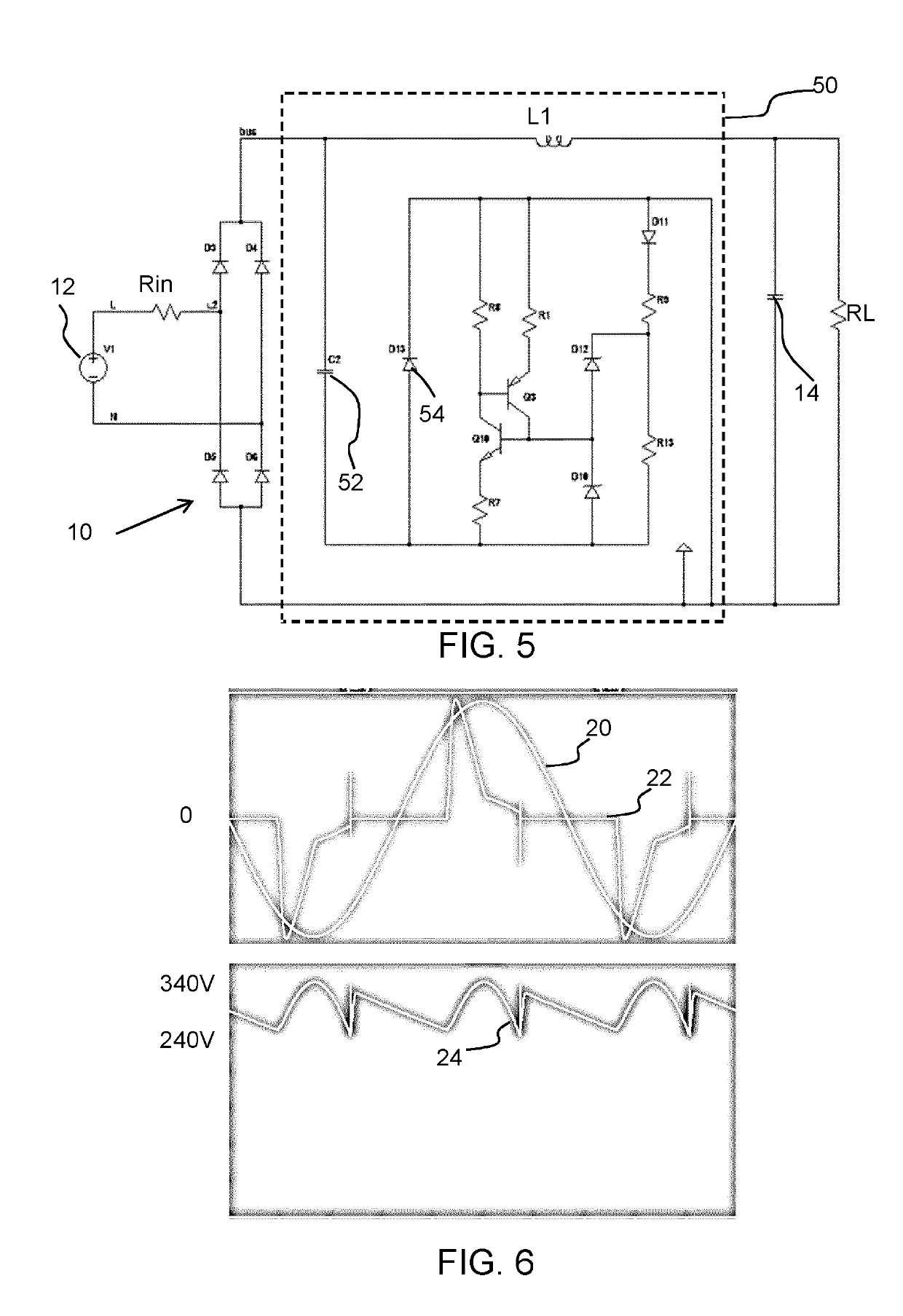
[0061]The invention provides an AC / DC converter and conversion method, in which an AC input current is rectified and shaped by a waveform shaping capacitor. A current source circuit is used to provide current to the output load and a bulk capacitor in parallel to the load. The current source circuit is switched on and off with timing which is dependent on the phase of the AC input signal. This enables a relatively high power factor, for example between 0.7 and 0.9, with low cost circuitry with few components.

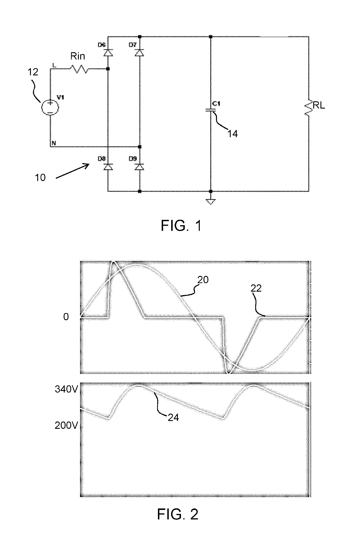
[0062]As explained above, there is a need to increase the power factor above 0.5 (which applies to the circuit of FIG. 1) but without adding excessive circuit complexity.

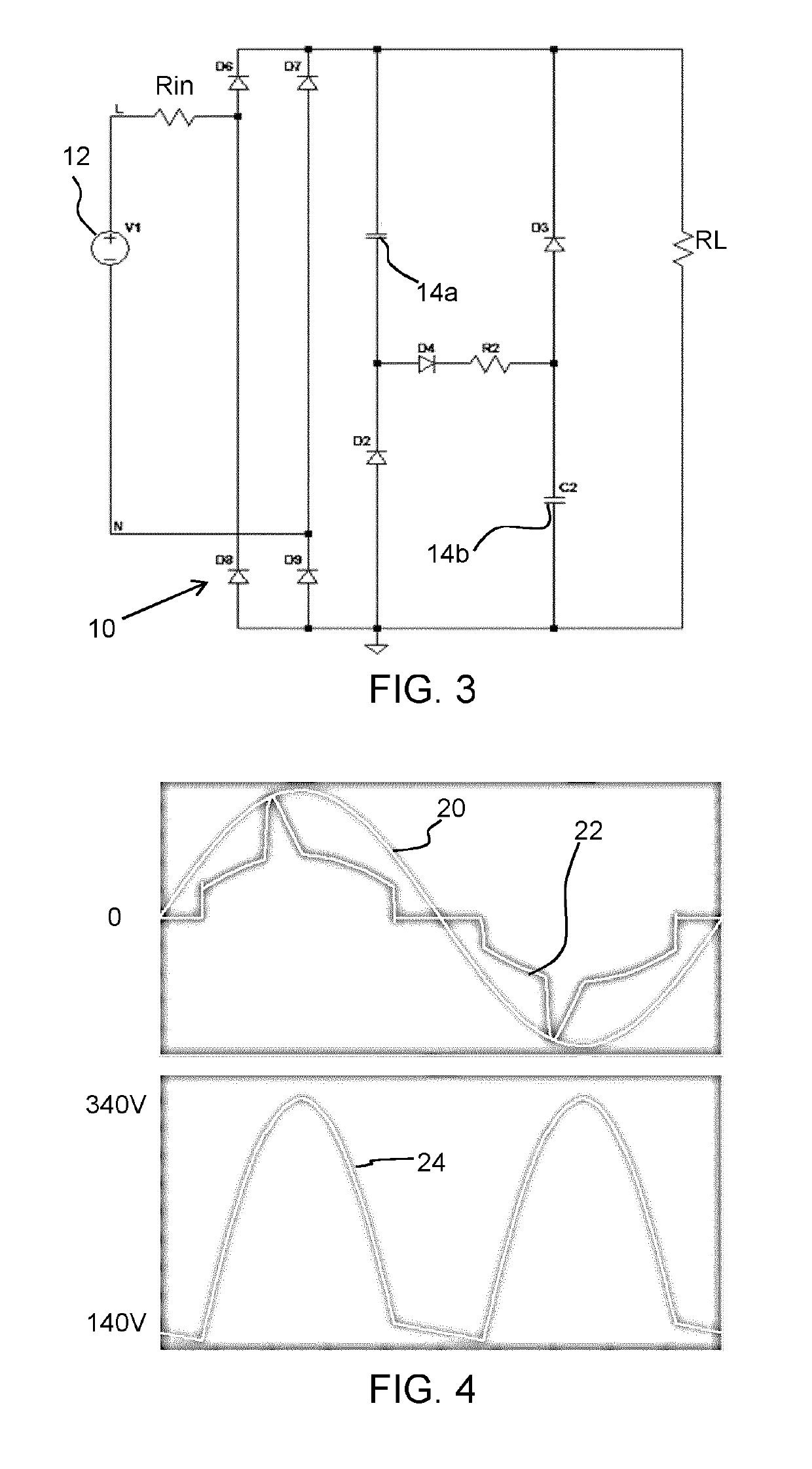
[0063]To improve the power factor, two common solutions are already typically used.

[0064]FIG. 3 shows an example of a so-called passive valley-fill circuit, in which an additional passive analog circuit is provided between two output capacitors 14a and 14b and the load, in the form of a network of resistors, dio...


PUM


Abstract

An AC/DC converter and conversion method are provided, in which an AC input is rectified and shaped by a waveform shaping capacitor. A current source circuit is used to provide the output current to the output load which has a parallel bulk capacitor. The current source circuit is switched on and off with timing which is dependent on the phase of the AC input signal. This enables a relatively high power factor, for example between 0.7 and 0.9, with low cost circuitry with few components.

Description

FIELD OF THE INVENTION[0001]This invention relates to power factor correction within AC / DC converters.BACKGROUND OF THE INVENTION[0002]There are many devices which require AC / DC conversion in order to be powered by the mains.[0003]This invention is of particular interest to LED lighting, in which an AC / DC converter supplies an LED driver. The LED driver for example comprises a resonant DC / DC converter, which can be configured or operated as a constant current source or a constant voltage source. A constant current source can be used to drive an LED arrangement directly, thus enabling a single stage driver. Constant voltage sources can be used, for example, for LED modules which have further driver electronics in order to ensure a corresponding power supply to the LEDs with a predetermined current from the output voltage provided by the constant voltage source.[0004]One function implemented within a power converter which is supplied with mains (or other AC) power is power factor corr...

Claims


Application Information

Patent Timeline
IPC IPC(8): H05B33/08H02M7/219H02M1/42H05B44/00
CPCH02M1/4225H05B33/0845H02M7/219H05B33/0815H02M1/081H02M1/4208H02M1/4266H02M3/156H02M7/21Y02B20/30Y02B70/10H05B45/357H05B45/375H05B45/3725H05B45/38H05B45/397H02M1/4291
Inventor SAUERLANDER, GEORGHATTRUP, CHRISTIAN
Owner SIGNIFY HLDG BV
Why Eureka
Try Eureka