
Control system and method for vehicles with dynamic braking

a control system and dynamic braking technology, applied in the field of vehicle control, can solve the problems of slowing the vehicle, abnormal braking choppers may not provide sufficient resistance to prevent a large power demand on the engine upon entering the propel mode, and the engine at the reduced idle speed associated with the dynamic braking mode may not be able to handle a significant power demand, etc., to achieve the effect of increasing the engine speed of the engine, increasing cooling, and increasing cooling

Active Publication Date: 2019-10-31
GE GLOBAL SOURCING LLC
View PDF0 Cites 7 Cited by
  • Summary
  • Abstract
  • Description
  • Claims
  • Application Information

AI Technical Summary

Benefits of technology

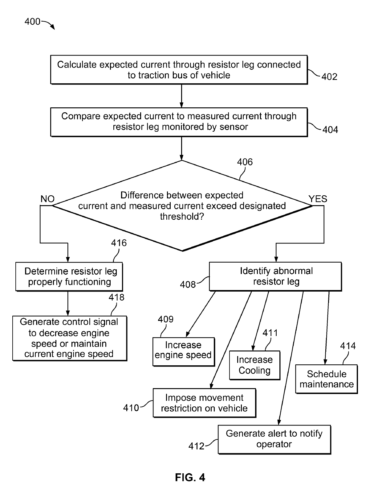
The patent describes a control system for vehicles that uses a current sensor to monitor the level of current in a resistor leg. This resistor leg is connected to the vehicle's traction bus and includes a braking chopper. The control system analyzes the measured current from the sensor and generates a control signal to increase engine speed, cool the resistance elements, prevent movement, or schedule maintenance for the resistor leg if there is a significant difference between the expected and measured current levels. The technical effect of this system is to improve the vehicle's ability to control its current and prevent damage to its electrical components.

Problems solved by technology

For example, the traction motors utilize mechanical energy from the rotation of the wheels to generate electrical energy, which slows the vehicle.
The engine at the reduced idle speed associated with the dynamic braking mode may not be able to handle a significant power demand.
If a braking chopper is defective or abnormal (i.e. one example would be a shorted chopper that is stuck in an “on” or conducting state), the abnormal braking chopper may not provide sufficient resistance to prevent a large power demand on the engine upon entering the propel mode.
The large power demand on the engine while the engine is at a reduced speed may cause the engine to stall and / or the alternator to collapse.
Stalling of the engine may disrupt not only the movement of the off-highway vehicle but also various vehicle systems that rely on continuous operation of the engine, such as hydraulic brakes and electrical control systems.

Method used


Image

  • Control system and method for vehicles with dynamic braking
  • Control system and method for vehicles with dynamic braking
  • Control system and method for vehicles with dynamic braking

Examples


Embodiment Construction

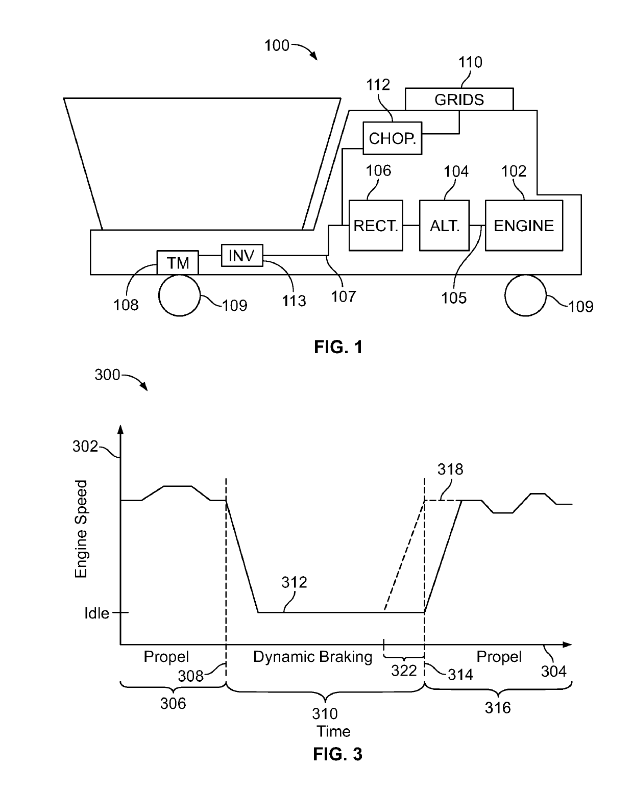
[0014]Reference will be made below in detail to example embodiments of the inventive subject matter, examples of which are illustrated in the accompanying drawings. Wherever possible, the same reference numerals used throughout the drawings refer to the same or like parts. Certain embodiments of the inventive subject matter are described with respect to off-highway vehicles designed to perform an operation associated with a particular industry, such as mining, construction, farming, etc., and may include haul trucks, cranes, earth moving machines, mining machines, farming equipment, tractors, material handling equipment, earth moving equipment, etc. However, the embodiments of the inventive subject matter are also applicable for use with other vehicles, such as on-road vehicles (e.g., automobiles, tractor-trailer rigs, on-road dump trucks, etc.), rail vehicles, and marine vehicles.

[0015]At least one technical effect provided by one or more embodiments described herein is detection o...


PUM


Abstract

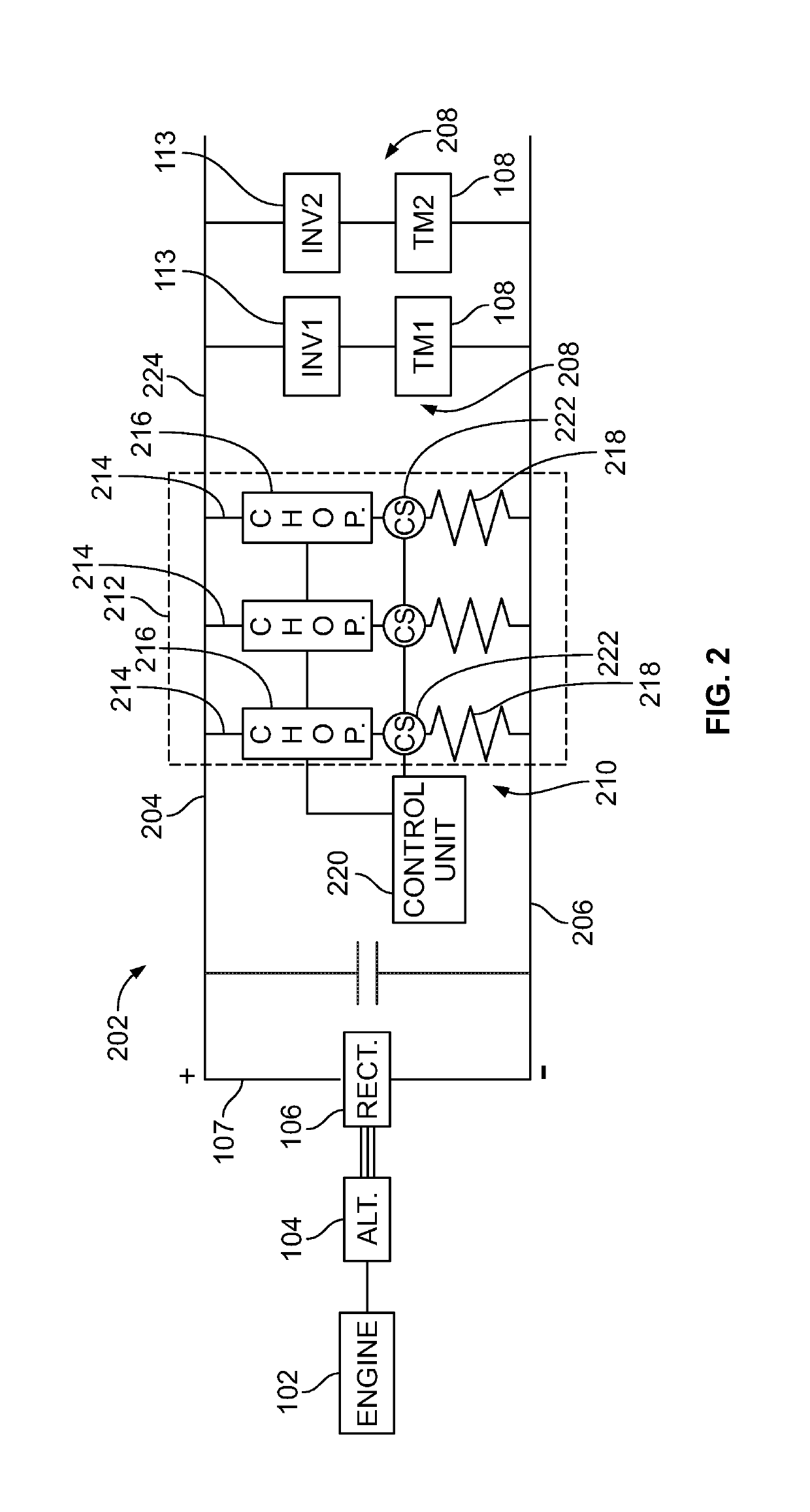
A control system includes a current sensor and one or more processors. The current sensor is configured to be disposed onboard a vehicle and to monitor a measured current conducted into a resistor leg of the vehicle. The resistor leg has a braking chopper and one or more resistive elements, and is connected with a traction bus of the vehicle. The one or more processors are configured to receive the measured current from the current sensor and, in response to the measured current differing from an expected current through the resistor leg, the one or more processors are configured to generate a control signal configured to one or more of increase an engine speed of an engine of the vehicle, increase cooling to the one or more resistive elements of the resistor leg, restrict movement of the vehicle, or schedule maintenance for the resistor leg.

Description

CROSS-REFERENCE TO RELATED APPLICATIONS[0001]This application claims priority to U.S. Provisional Patent Application No. 62 / 663,761, which was filed 27-Apr.-2018, and the entire disclosure of which is incorporated herein by reference.FIELD[0002]Embodiments of the inventive subject matter described herein generally relate to vehicle control. Certain embodiments relate to systems and methods for controlling off-highway vehicles that utilize braking choppers for dynamic braking modes of operation.BACKGROUND[0003]In the mining industry, large off-highway vehicles typically employ electrically motorized wheels for propelling and slowing the vehicle. For example, the off-highway vehicles may include large horsepower diesel engines in conjunction with alternators, rectifiers, inverters, and the like, that are connected to the wheels of the vehicles via traction motors. The alternator converts mechanical energy into electrical energy that is transmitted to the traction motors which transfor...

Claims


Application Information

Patent Timeline
IPC IPC(8): B60L7/08B60L15/20B60L7/22
CPCB60L7/22B60L7/08B60L15/2009B60W20/00B60W20/50B60W10/06B60W10/08B60W10/18B60W50/14B60W2050/143B60W2510/18B60W2710/0644B60W2710/08B60L3/0076B60L2200/36B60L50/61B60L50/53B60L3/12B60L1/02B60L2200/40B60L2240/36B60L2240/441B60L2260/26B60L2260/44Y02T10/70Y04S10/126Y02E60/00
Inventor PETRAK, EDWARD THOMASYOUNG, HENRY TODDWOLFF, JEFFREY
Owner GE GLOBAL SOURCING LLC
Learn More