Louvered Panel Assembly

a technology of louvered panels and louvered roofs, which is applied in the direction of roofs, sunshades, construction, etc., can solve the problems of increasing the load of the roof assembly, increasing the wear and tear of the rotatable surfaces, and causing the roof to fall or cave in, so as to improve the interlocking structure and improve the structural design

Active Publication Date: 2019-11-07
SUNDANCE LOUVERED ROOFS LLC
View PDF0 Cites 19 Cited by
  • Summary
  • Abstract
  • Description
  • Claims
  • Application Information

AI Technical Summary

Benefits of technology

[0008]The present invention is a mounted roof system with a plurality of louvers which includes interconnecting structure to allow the louvers to open and close in a synchronized manner as desired. The mounted roof system can be mounted to a wall, an eave or may be free standing over an area. The interlocking louvers having

Problems solved by technology

However, many of these systems have a large amount of friction which increases the wear and tear upon the rotatable surfaces but also upon the power equipment as they cause additional drag to the power equipment and require additional power for rotation of the louvers.
However, installing electrical cords and hanging light fixtures around or from the louvers may create an electrical hazard, impact the rotation of the louvers or cause them to fail under the weight of the hanging light fixtures.
Some of this debris may become lodged into the rotational surfaces or the louvers which can restrict flow of water or cause water to buildup, increasing the load of the roof assembly and potentially causing the roof to fall or cave-in.
In some environments, built-up water may become frozen and expand, causing various mechanical or s

Method used


Image

  • Louvered Panel Assembly
  • Louvered Panel Assembly
  • Louvered Panel Assembly

Examples


Embodiment Construction

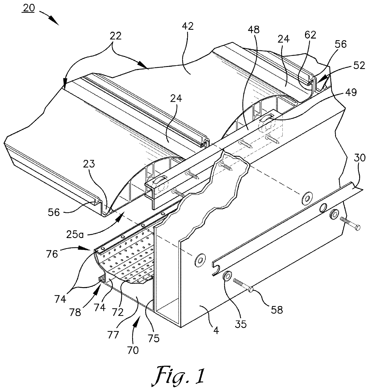
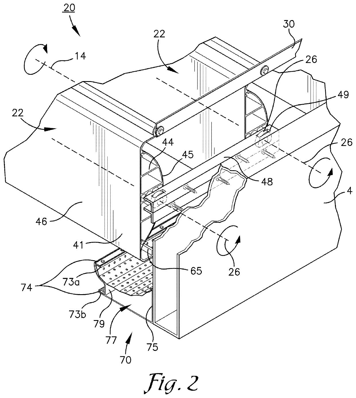
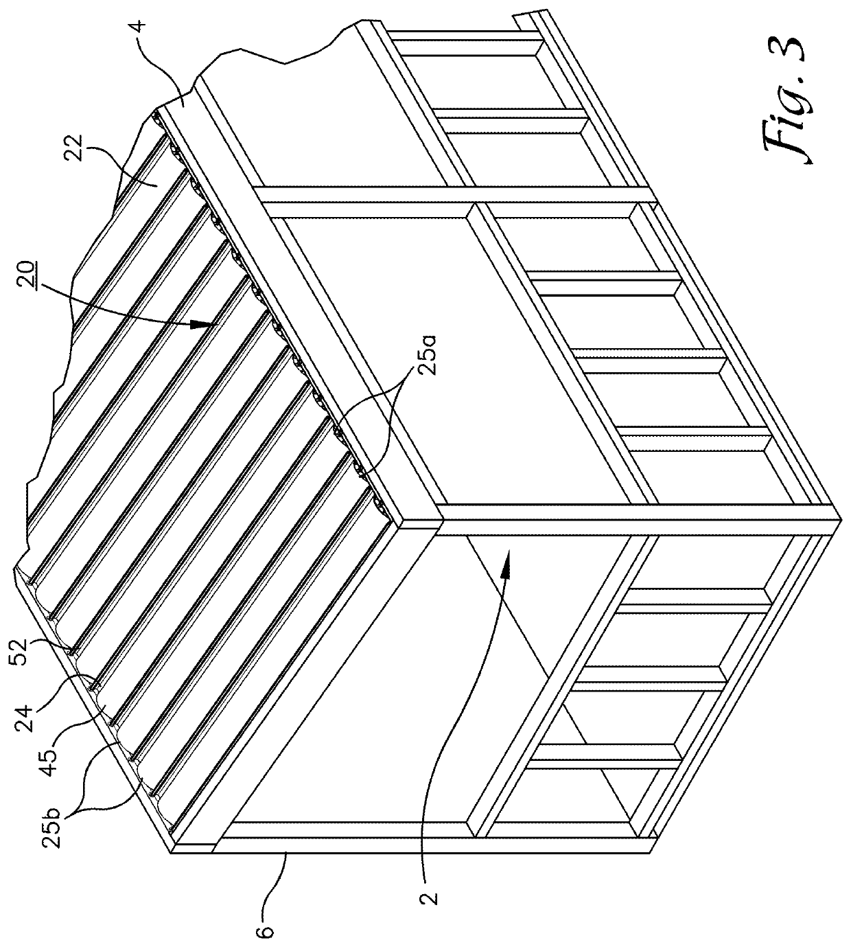
[0023]As required, detailed embodiments of the present invention are disclosed herein; however, it is to be understood that the disclosed embodiments are merely exemplary of the invention, which may be embodied in various forms. It will be readily understood that the components of the present invention, as generally described and illustrated in the figures herein, may be arranged and designed in a wide variety of different configurations. Thus, the following specific structural and functional details disclosed herein (including the drawings) are not to be interpreted as limiting, but merely representative of the selected embodiments of the invention and as a basis for the claims and as a representative basis for teaching one skilled in the art to variously employ the present invention in virtually any appropriately detailed structure.

[0024]The features, structures or characteristics of the invention described throughout this specification may be combined in any suitable manner in on...


PUM


Abstract

The present invention provides an improved louvered panel assembly comprising at least a first louver and a second louver with a control arm extending between each of them and each presenting a central receiver configured for receipt of a first bearing surface configured for rotation of them about a rotational axis extending through each of them. A leading projection extends from the first louver and is configured for downward rotation as the first louver operates between an open and a closed position. A trailing projection extends from the second louver, the trailing projection configured for upward rotation as the second louver operates between an open and a closed position the trailing projection presenting an upper channel which is adapted for receipt of a sealing membrane. An engaging structure is presented by said leading projection and said trailing projection which at least partially seals the panel assembly with the sealing membrane while the first and second louvers are in the closed position.

Description

FIELD OF THE INVENTION[0001]The present invention is broadly directed to adjustable louvered roof structures and more particularly to a novel improved adjustable louvered roof system with an improved bearing system, the roof system being easier to maintain.BACKGROUND OF THE INVENTION[0002]Conventional louvered roof assemblies include parallel louvers which are rotated between an open and closed position, as desired. However, many of these systems have a large amount of friction which increases the wear and tear upon the rotatable surfaces but also upon the power equipment as they cause additional drag to the power equipment and require additional power for rotation of the louvers. Therefore, there exists a need to reduce the friction upon the rotatable surfaces.[0003]Some louvered roof assemblies are installed in an outdoor environment where they provide shade and shelter from the underlying area. These roof assemblies also provide shade from the sun. Additionally, these roof assemb...

Claims


Application Information

Patent Timeline
IPC IPC(8): E04F10/10
CPCE04F10/10E04B7/163E04D13/064E04D13/076
Inventor TORMAN, HALBRINKMAN, CASS
Owner SUNDANCE LOUVERED ROOFS LLC
Why Eureka
Try Eureka