Electrical isolation mounting of electrical machine stator

a technology of electrical machine stator and mounting plate, which is applied in the direction of mechanical equipment, machines/engines, prevention/reduction of eddy current losses in winding heads, etc., can solve the problems of affecting the service life of the generator, difficult to make an electrical isolation between the nacelle and the stator housing, and high problems, so as to minimize stray currents

Active Publication Date: 2019-11-21
VESTAS WIND SYST AS
View PDF0 Cites 6 Cited by
  • Summary
  • Abstract
  • Description
  • Claims
  • Application Information

AI Technical Summary

Benefits of technology

[0016]A second aspect relates to a method for minimizing stray currents in an electrical machine in a wind turbine, wherein said electrical machine comprises a stator (702) with one or more electrical winding(s) (704), said electrical winding(s) being arranged to be connected to an electrical grid (760) by at

Problems solved by technology

Due to size and loads in a modern multi watt wind turbine, it is difficult to make an electrical isolation between the nacelle and the stator housing.
However, the well known ways of grounding the stationary and rotating parts may often create problems in relation to

Method used


Image

  • Electrical isolation mounting of electrical machine stator
  • Electrical isolation mounting of electrical machine stator
  • Electrical isolation mounting of electrical machine stator

Examples


Embodiment Construction

[0026]The present invention will now be explained in further details. While the invention is susceptible to various modifications and alternative forms, specific embodiments have been disclosed by way of examples. It should be understood, however, that the invention is not intended to be limited to the particular forms disclosed.

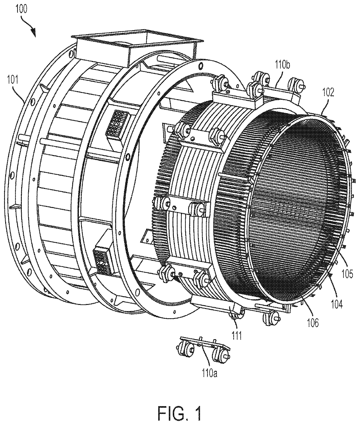
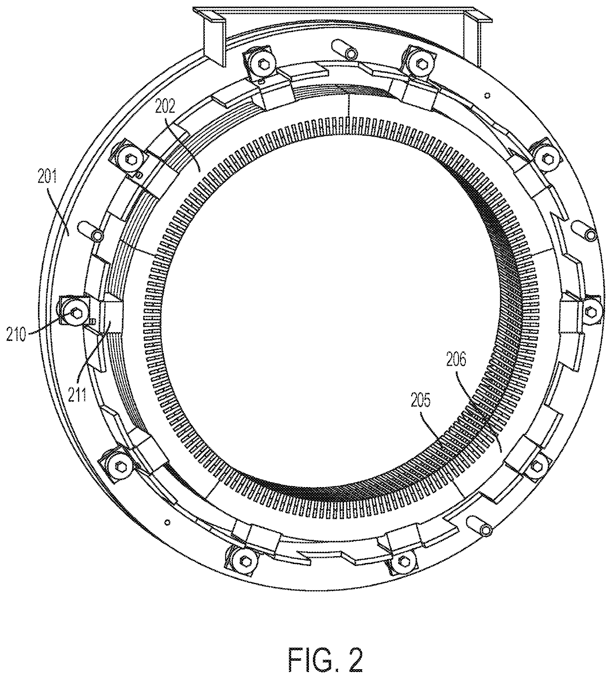
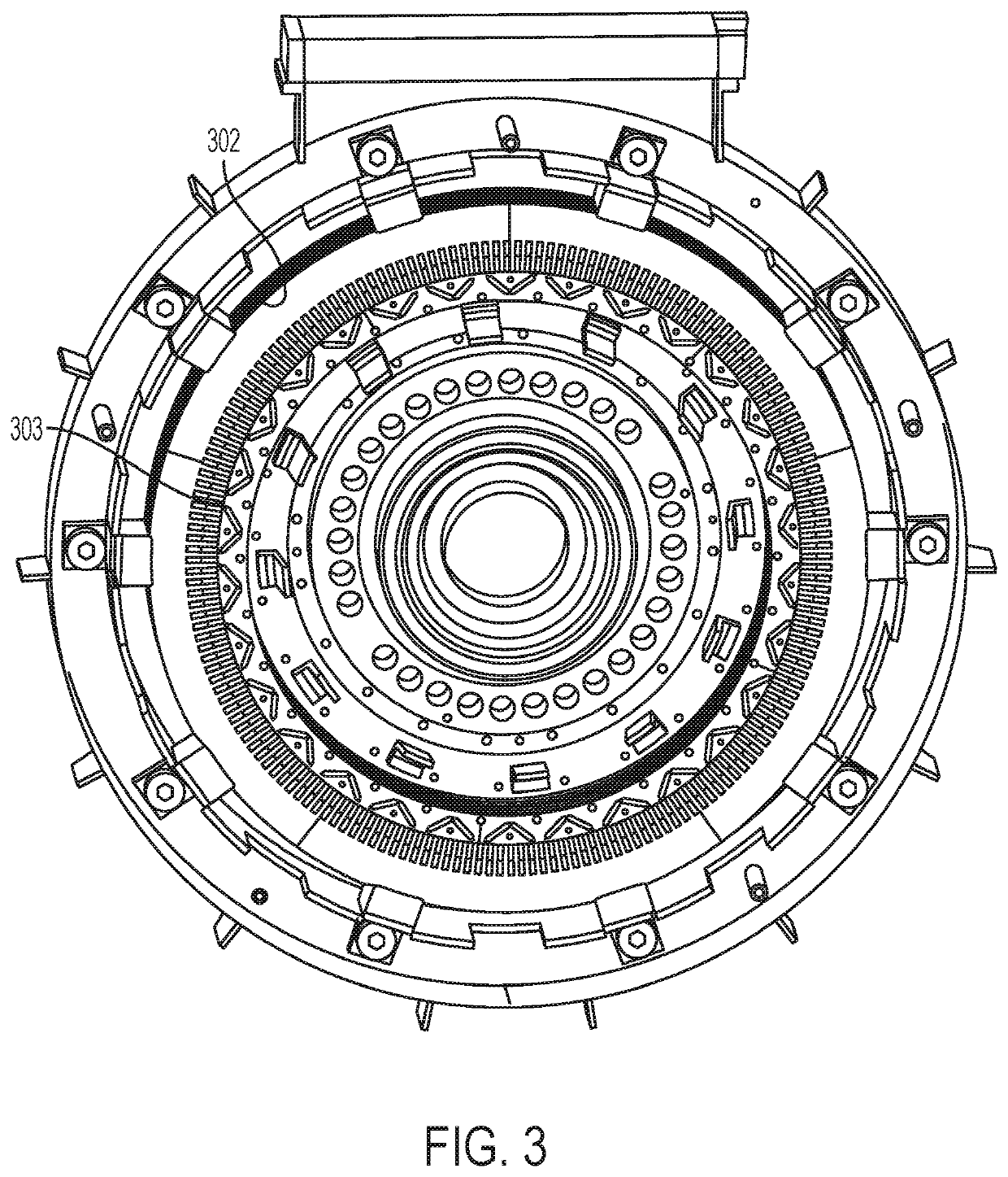
[0027]Electrical generators most often comprise a rotor, a stator and a stator housing, where the purpose of the stator and rotor is known to the skilled person, and the housing provides structural support for the stator and together with end shields and bearings, it also provides support for the rotor, and ensures alignment between the rotor and the stator.

[0028]Furthermore the housing also provides the means for fixation of the generator 12 to the bed frame of the wind turbine nacelle 5.

[0029]The magnetic circuit of the electrical machine includes a laminated stator stack and a laminated rotor stack. These consist of laminated electrical sheets. Depending ...


PUM


Abstract

The present invention relates to a wind turbine with an electrical machine wherein said electrical machine comprises a stator (702) with one or more electrical winding(s) (704), said electrical winding(s) being arranged to be connected to an electrical grid (760) by at least one cable (740) with at least one phase conductor (746), the at least one cable (740) comprises at least one return path (744) to conduct leakage currents, and at least one electrical shield (745), the stator being electrically isolated from a stator housing (701). The invention also relates to a method for minimizing stray currents in an electrical machine in a wind turbine.

Description

BACKGROUND OF THE INVENTION[0001]Electrical generators in wind turbines are often hard mounted to the bedframe of the wind turbine nacelle. This means that there are very good electrical connections between the two. Due to size and loads in a modern multi watt wind turbine, it is difficult to make an electrical isolation between the nacelle and the stator housing. The electrical design of the wind turbine therefore have to take into account that there is a pathway for stray current between the bedframe and the generator housing.[0002]Typically, modern wind turbines are connected to an electric utility grid in order to be able to generate and supply electricity to consumers located remotely from the wind turbines.[0003]The rotor speed of the wind turbine increases and decreases with changing wind speed in order to subtract as much energy from the wind as possible, and consequently the electric generator generates electricity with a variable frequency. The electricity is converted by ...

Claims


Application Information

Patent Timeline
IPC IPC(8): H02K3/42H02K7/18H02K3/38H02K3/50H02K5/24H02K7/00H02K7/116H02K11/04F03D9/25
CPCH02K3/42H02K2203/15F03D9/255H02K5/24H02K3/50H02K7/003H02K7/116H02K3/38H02K11/046H02K7/1838F05B2220/7062H02K5/08H02K7/183H02M7/003Y02E10/76Y02E10/72H02K11/0141H02M1/123H02K11/05H02K11/00
Inventor SIMONSEN, LARS DYREDMONGEAU, PETER
Owner VESTAS WIND SYST AS
Why Eureka
Try Eureka