
Substrate manufacturing apparatus and methods with factory interface chamber heating

a manufacturing apparatus and chamber heating technology, applied in the field of electromechanical device manufacturing, can solve problems such as performance problems of systems, and achieve the effect of reducing or stopping the heating of purge gas

Pending Publication Date: 2019-11-28
APPLIED MATERIALS INC
View PDF6 Cites 147 Cited by
  • Summary
  • Abstract
  • Description
  • Claims
  • Application Information

AI Technical Summary

Benefits of technology

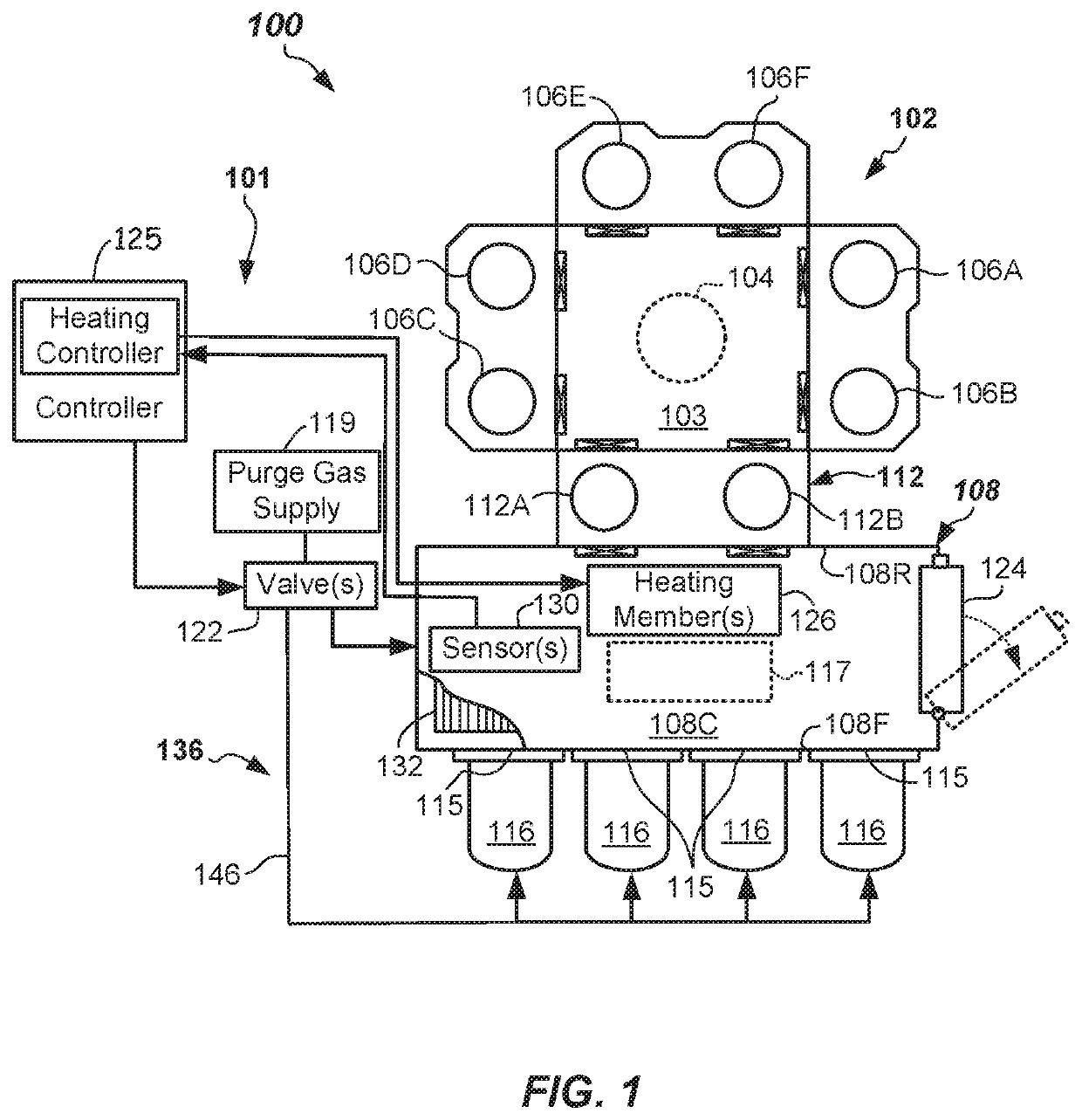
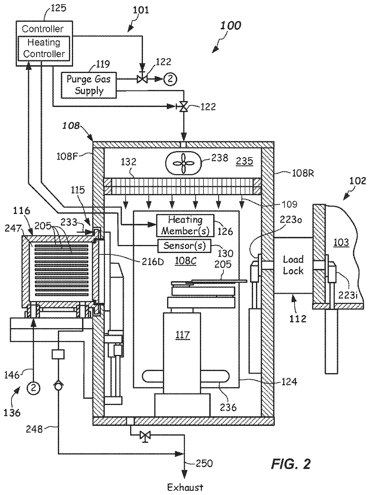
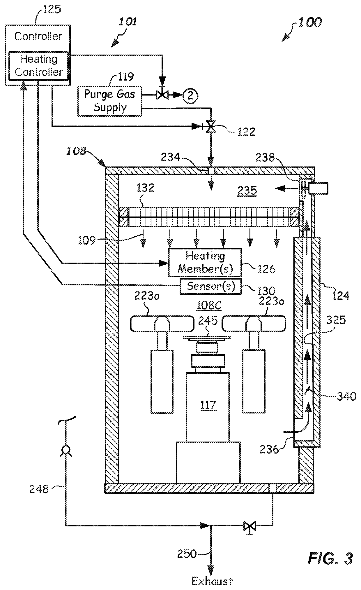
The patent describes an apparatus and method for purging air from a factory interface chamber. This involves heating the air using heating elements and a purge gas heating apparatus. The apparatus can be used to control the purge gas temperature and can be accessed through an access door for servicing. The technical effects of the patent include improved purge control and efficiency in purging air from the factory interface chamber.

Problems solved by technology

However, such systems can suffer from certain performance problems.

Method used


Image

  • Substrate manufacturing apparatus and methods with factory interface chamber heating
  • Substrate manufacturing apparatus and methods with factory interface chamber heating
  • Substrate manufacturing apparatus and methods with factory interface chamber heating

Examples


Embodiment Construction

[0021]Reference will now be made in detail to the example embodiments, which are illustrated in the accompanying drawings. Wherever possible, the same or like reference numbers will be used throughout the drawings to refer to the same or like parts throughout the several views. Features shown in the various embodiments herein can be combined with each other unless specifically noted otherwise.

[0022]Existing electronic device manufacturing systems may suffer from problems when a high relative humidity level, high oxygen (O2) level, and / or a high level of other chemical contaminant are observed. In particular, exposure of substrates to relatively high humidity levels, relatively high O2 levels, and / or other chemical contaminants and particulates can adversely affect substrate properties.

[0023]Accordingly, certain electronic device processing apparatus provide efficiency and / or processing improvements in the manufacturing of substrates by controlling certain environmental conditions to...


PUM

PropertyMeasurementUnit
Temperatureaaaaaaaaaa

Abstract

Electronic device processing apparatus including a factory interface chamber purge apparatus with purge gas heating. The factory interface chamber purge apparatus includes one or more heating elements configured to heat the purge gas. In some embodiments, the provision of heated purge gas to the chamber filter assembly can rapidly reduce moisture contamination after the access door is opened for factory interface servicing. In further embodiments, the provision of heated purge gas to the factory interface chamber can aid in desorbing certain chemical compounds from the substrates following processing when a low-humidity environment is provided. Purge control methods and apparatus are described, as are numerous other aspects.

Description

RELATED APPLICATIONS[0001]This application claims the benefit of U.S. Provisional Application No. 62 / 676,731, filed May 25, 2018, the entire contents of which are incorporated herein by reference.FIELD[0002]Embodiments relate to electronic device manufacturing, and more specifically to factory interface apparatus and methods including environmental control. Related Applications.BACKGROUND[0003]Processing of substrates in semiconductor component manufacturing is carried out in process tools. Substrates travel between the process tools in substrate carriers (e.g., Front Opening Unified Pods or FOUPs), which can dock to a factory interface of the tool, otherwise referred to as an equipment front end module (EFEM). The factory interface includes a factory interface chamber that can contain a load / unload robot that is operable to transfer substrates between the respective FOUPs docked at a load port of the factory interface and one or more load locks or process chambers, for example. In ...

Claims


Application Information

Patent Timeline
IPC IPC(8): H01L21/67H01L21/677B01D46/42
CPCB01D46/4263B01D2279/35H01L21/67017H01L21/67109H01L21/67196H01L21/67248H01L21/67763H01L21/67103H01L21/67766H01L21/67028H01L21/67098H01L21/67253H01L21/67276H01L21/67772
Inventor REUTER, PAUL B.MERRY, NIRRICE, MICHAEL R.HRUZEK, DEAN C.
Owner APPLIED MATERIALS INC
Learn More