Automatic Advance Angle Control System And Method For Brushless Linear Direct Current Motor

a direct current motor and automatic technology, applied in the direction of electronic commutator control, electronic commutator speed/torque control, electronic commutator control, etc., can solve the problems of torque ripple, current delay of electric torque generated by bldc motor, and inability to correct advance angle control, etc., to achieve efficient operation and efficient operation

Active Publication Date: 2019-11-28
PUSAN NAT UNIV IND UNIV COOPERATION FOUND
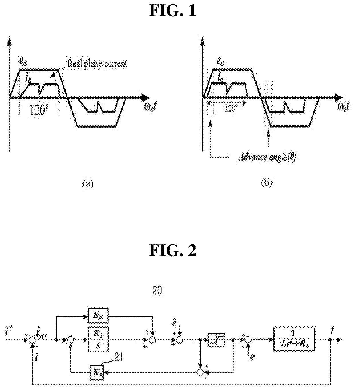
View PDF0 Cites 2 Cited by
  • Summary
  • Abstract
  • Description
  • Claims
  • Application Information

AI Technical Summary

Benefits of technology

[0010]It is an object of the present disclosure to provide an automatic advance angle control system for a brushless linear direct current (BLDC) motor which efficiently operates in a high-speed operation region through automatic advance angle control without using a lookup table or an additional circuit.
[0011]It is another object of the present disclosure to provide an automatic advance angle control method for a BLDC motor which efficiently operates in a high-speed operation region through automatic advance angle control without using a lookup table or an additional circuit.

Problems solved by technology

The electric torque generated by the BLDC motor may have current delay due to an increase in reactance of a phase winding in a high-speed operation region.
The delay of the phase current ib may cause a torque ripple.
When an operating point is changed due to a change in operating temperature of the motor, the advance angle control may not be correct.
Also, when an additional circuit connected to a hall sensor is used, it is necessary to accurately determine when an advance angle is applied, and the volume and cost of the entire motor system increase due to the need for additional circuitry.

Method used


Image

  • Automatic Advance Angle Control System And Method For Brushless Linear Direct Current Motor
  • Automatic Advance Angle Control System And Method For Brushless Linear Direct Current Motor
  • Automatic Advance Angle Control System And Method For Brushless Linear Direct Current Motor

Examples


Embodiment Construction

[0025]Advantages and features of the present disclosure and methods of accomplishing the same will be apparent by referring to embodiments described below in detail in connection with the accompanying drawings. The disclosure may, however, be embodied in different forms and should not be construed as limited to the embodiments set forth herein. Rather, these embodiments are provided so that this disclosure will be thorough and complete, and will fully convey the scope of the present disclosure to those skilled in the art. Therefore, the scope of the disclosure is defined only by the appended claims. The size and relative size of the constituent elements marked in the drawings may be exaggerated for clarity of description. Like reference numerals refer to like elements throughout the specification, and the term “and / or” includes any and all combinations of one or more of the associated listed items.

[0026]The terminology used herein is for the purpose of describing particular embodime...


PUM


Abstract

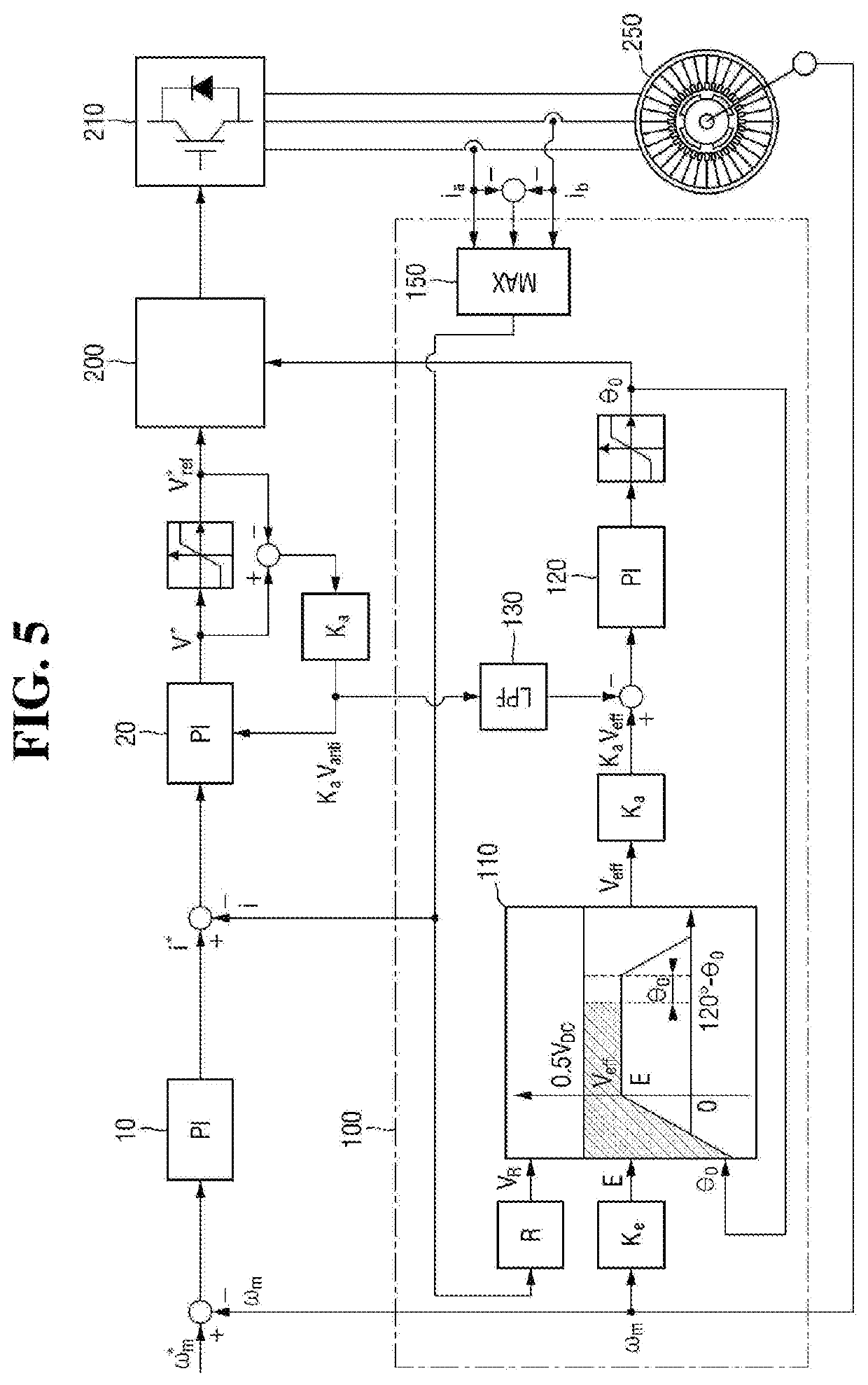
Provided are an automatic advance angle control system and method for a brushless linear direct current (BLDC) motor. The automatic advance angle control system for the BLDC motor includes a current controller configured to generate an anti-windup output for compensating for accumulated errors of an output voltage provided to the BLDC motor; a voltage headroom calculator configured to generate a voltage headroom from a counter-electromotive force and the output voltage provided to the BLDC motor; and an advance angle controller configured to generate an advance angle for controlling a phase of a phase current of the BLDC motor by performing proportional integration on a difference between the anti-windup output and the voltage headroom when the anti-windup output is generated and configured to ignore the generation of the advance angle when the anti-windup output is not generated.

Description

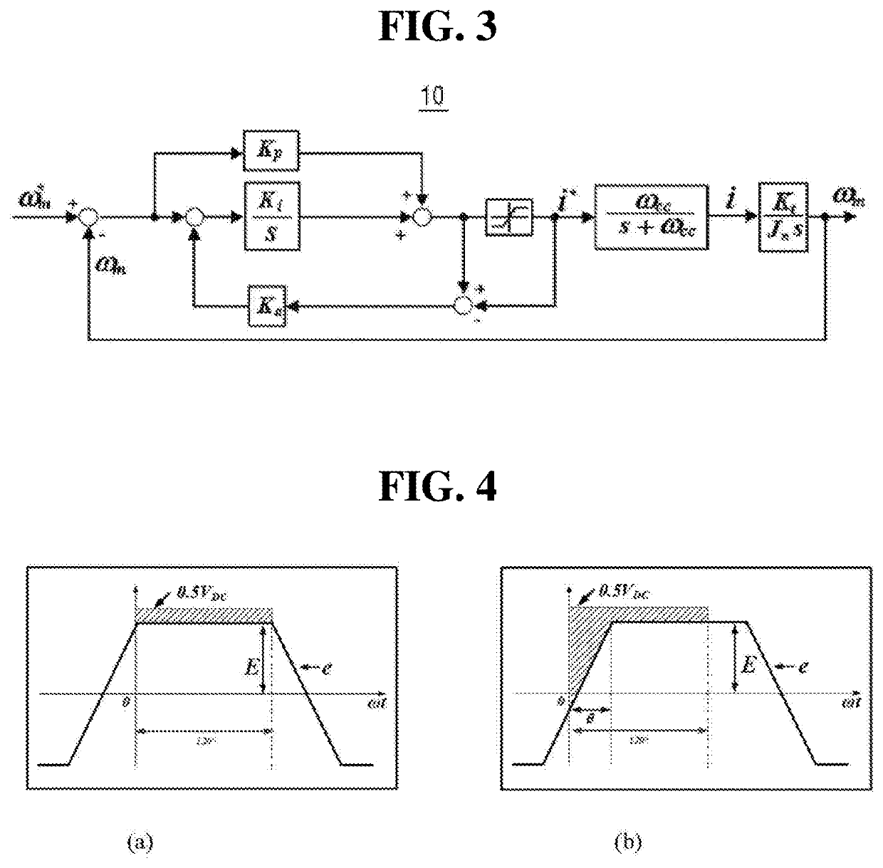
[0001]This application claims priority from Korean Patent Application No. 10-2018-0058515 filed on May 23, 2018 in the Korean Intellectual Property Office, the disclosure of which is incorporated herein by reference in its entirety.BACKGROUND1. Field of the Disclosure[0002]The present disclosure relates to an automatic advance angle control system and method for a brushless linear direct current motor.2. Description of the Related Art[0003]Generally, a brushless direct current (BLDC) motor is an electrically driven motor, which is a DC motor from which mechanical contact parts such as a brush and a commutator are removed.[0004]FIG. 1 shows graphs illustrating operation of a BLDC motor.[0005]Referring to FIG. 1(a), the BLDC motor generates electrical torque by the product of a quasi-trapezoidal counter-electromotive force ea and a quasi-square wave-shaped phase current ia. That is, an ideal BLDC motor can uniformly generate torque by applying a square wave-shaped phase current ia to ...

Claims


Application Information

Patent Timeline
Patent Type & Authority Applications(United States)
IPC IPC(8): H02P7/293H02P7/02H02P7/29
CPCH02P7/29H02P7/02H02P7/293H02P6/08H02P6/15H02P6/182
Inventor MOK, KIM JANG
Owner PUSAN NAT UNIV IND UNIV COOPERATION FOUND
Why Eureka
Try Eureka