
Radiovision device

a radio wave and device technology, applied in the direction of direction finders using radio waves, 2d-image generation, instruments, etc., can solve the problems of inefficient large-bandwidth devices and limited device siz

Active Publication Date: 2019-12-05
UNIVERSITY OF CHILE
View PDF30 Cites 5 Cited by
  • Summary
  • Abstract
  • Description
  • Claims
  • Application Information

AI Technical Summary

Benefits of technology

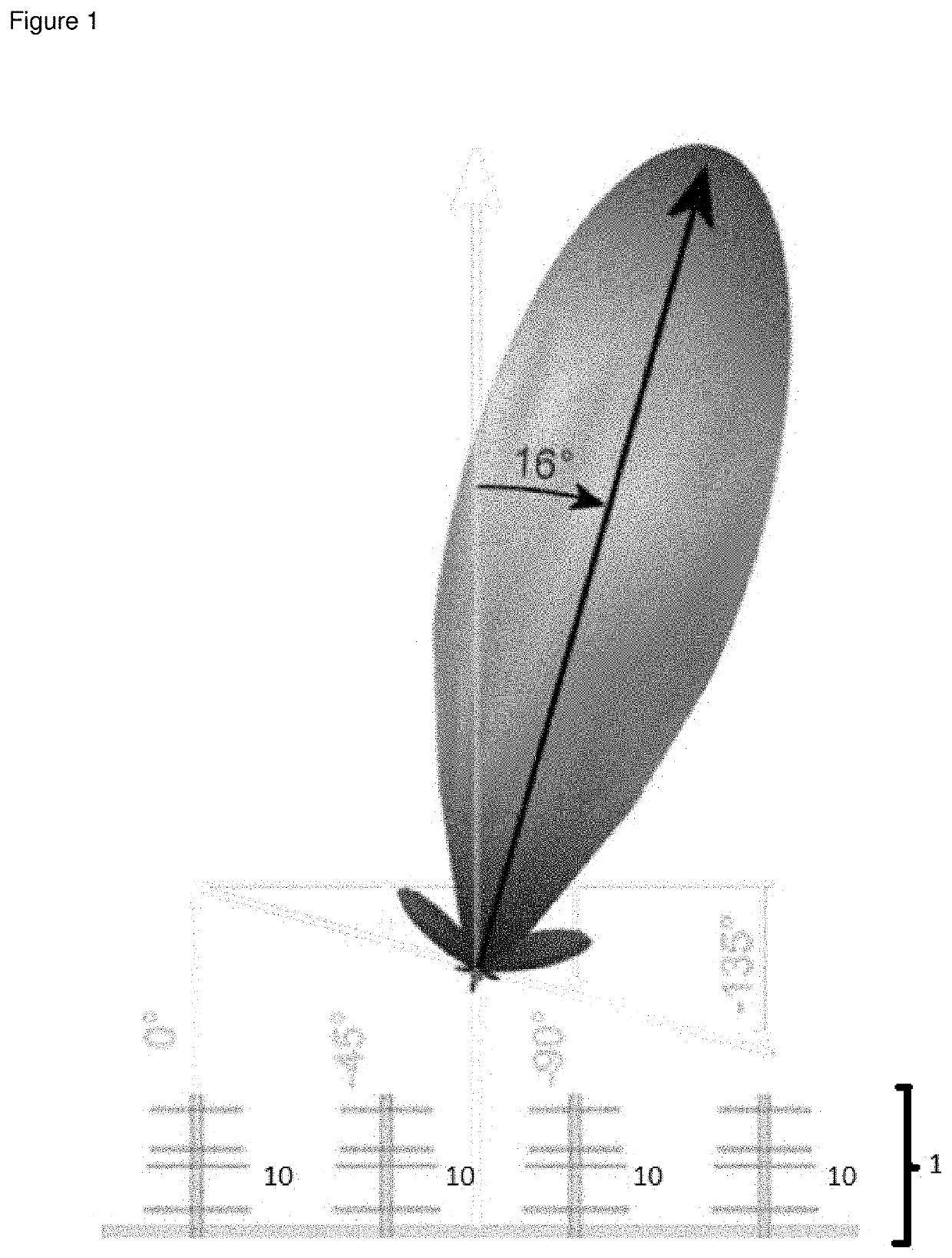
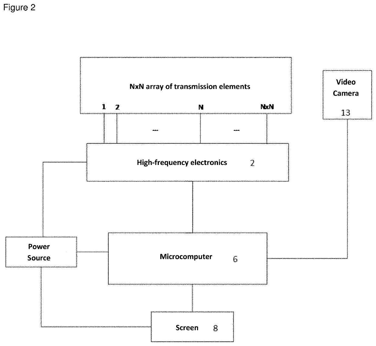
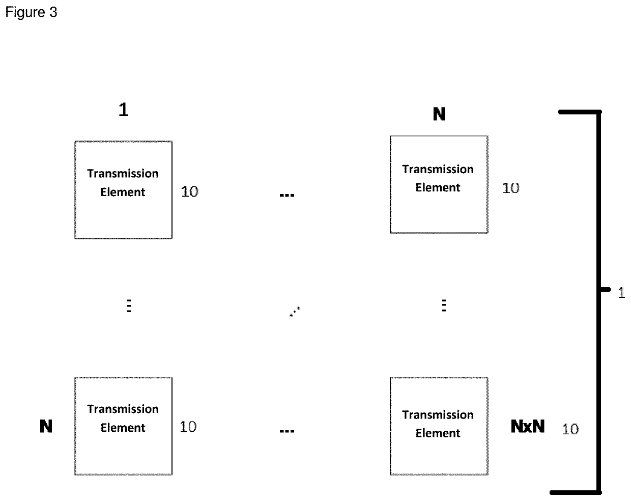
The patent describes a flat array of antennas that can detect electromagnetic emissions of all the bands to be detected (multi-band antennas, similar to cellular antennas). The antennas are positioned in different shapes to improve the quality of the synthesized beam. The array of antennas is compact enough to be part of a portable device. The patent also mentions a video camera that can be positioned above, below or at the center between the antennas, and a power supply that allows the system to remain autonomous and power the radio frequency electronics, camera, and microcomputer.

Problems solved by technology

This is very inefficient for large bandwidths.
This is all compacted, and the size of the device is only limited by the size of the substrate.

Method used


Image

  • Radiovision device
  • Radiovision device
  • Radiovision device

Examples


application example

[0130]One application example of this device without restricting its components is implemented using an array of 16 microstrip antennas, two high frequency electronic boards with commercial components and a commercial microcomputer.

[0131]Images of the design of this device are shown in FIGS. 6 / 10, 7 / 10 and 8 / 10.

[0132]The microstrip antennas correspond to rectangular antennas tuned to 1.88 GHz and with an approximate bandwidth of 50 MHz. FIG. 5 / 10

[0133]The first high frequency electronic board has 16 Analog® HMC631LP3 vector modules, which allow shifting the phase and amplitude of the signal received by each of the antennas. These modulators are controlled with digital potentiometers DS3930 by Maxim®, which communicate with an I2c bus. The signal is then combined in-phase using 14 TCP-2-272 power combiners by Minicircuits®. The signal is then amplified with a low noise amplifier (LNA) model MAAL-007304 by MACOM®.

[0134]The second board has a Linear® LT5538 model power detector and is ...


PUM


Abstract

This patent concerns a compact and portable system for real-time detection and location of electromagnetic emissions in the spectrum used by mobile devices (cell phones and Wi-Fi / Bluetooth devices). The principle of detection and location is based on phased array technology, which enables the synthesis of a directional radiation beam that can be electrically controlled in terms of both its shape and direction. This technology is used primarily in military and astronomical applications. The device also includes localization and control algorithms. This device will allow for detecting and locating electromagnetic emissions by means of an antenna beam scan within a field of view of 80×80 degrees. Once the detection and location have been established, the results are overlaid to a visual image captured by a video camera.

Description

SCOPE OF APPLICATION[0001]The application scope of this device includes industrial applications for the rescue of people trapped in snow avalanches or collapsed buildings and the detection and measurement of electromagnetic emissions from electrical sources or mobile devices in places where their use is not permitted, such as prisons or airplanes. On the other hand, this invention concerns the detection and location of RF (Radio Frequency) sources within the cellular telephony spectrum and the real time overlay of a visual representation in the form of an image.DESCRIPTION OF THE PRIOR ART[0002]The prior art mentions makes reference to several patents that protect not a particular physical system, but a set of devices and methods that allow a particular type of operation.[0003]There are a number of documents that lie within the general field of antennas, such as: EP 0 938 156, EP 0 144 867, US 2015 / 0022421, WO 2016 / 089464, WO 2011 / 148248.[0004]On the other hand, there are a number o...

Claims


Application Information

Patent Timeline
Patent Type & Authority Applications(United States)
IPC IPC(8): G01S3/72G06T11/20G01S3/78
CPCG01S3/78G01S3/72G06T11/206G01S3/046G01S3/46G01S3/02
Inventor FINGER, RICARDOMONASTERIO, DAVIDMUÑOZ, CHRISTOPHERFUENTES, ROBERTOREYES, NICOLÁSBRONFMAN, LEONARDOMENA, PATRICIO
Owner UNIVERSITY OF CHILE
Learn More