Ultrasonic bonding device and ultrasonic bonding method

a technology of ultrasonic bonding and ultrasonic bonding, which is applied in the direction of non-electric welding apparatus, manufacturing tools, instruments, etc., can solve the problems of short-circuit failure between wirings and smaller pitch intervals of wiring patterns, and achieve the effect of easy electrical connection of flat members

Active Publication Date: 2019-12-12
TDK CORPARATION
View PDF1 Cites 1 Cited by
  • Summary
  • Abstract
  • Description
  • Claims
  • Application Information

AI Technical Summary

Benefits of technology

[0005]The present invention has been achieved under such circumstances. It is an object of the invention to provide an ultrasonic bonding device and an ultrasonic bonding method capable of easily electrically connecting flat members without generation of short-circuit failure or so even if a wiring pitch interval is small.

Problems solved by technology

In recent years, however, a pitch interval of wiring patterns has been smaller, and a short-circuit failure between wirings has been becoming a problem in connection by ACF.

Method used


Image

  • Ultrasonic bonding device and ultrasonic bonding method
  • Ultrasonic bonding device and ultrasonic bonding method
  • Ultrasonic bonding device and ultrasonic bonding method

Examples


Embodiment Construction

[0039]Hereinafter, the present invention is described based on an embodiment shown in the figures.

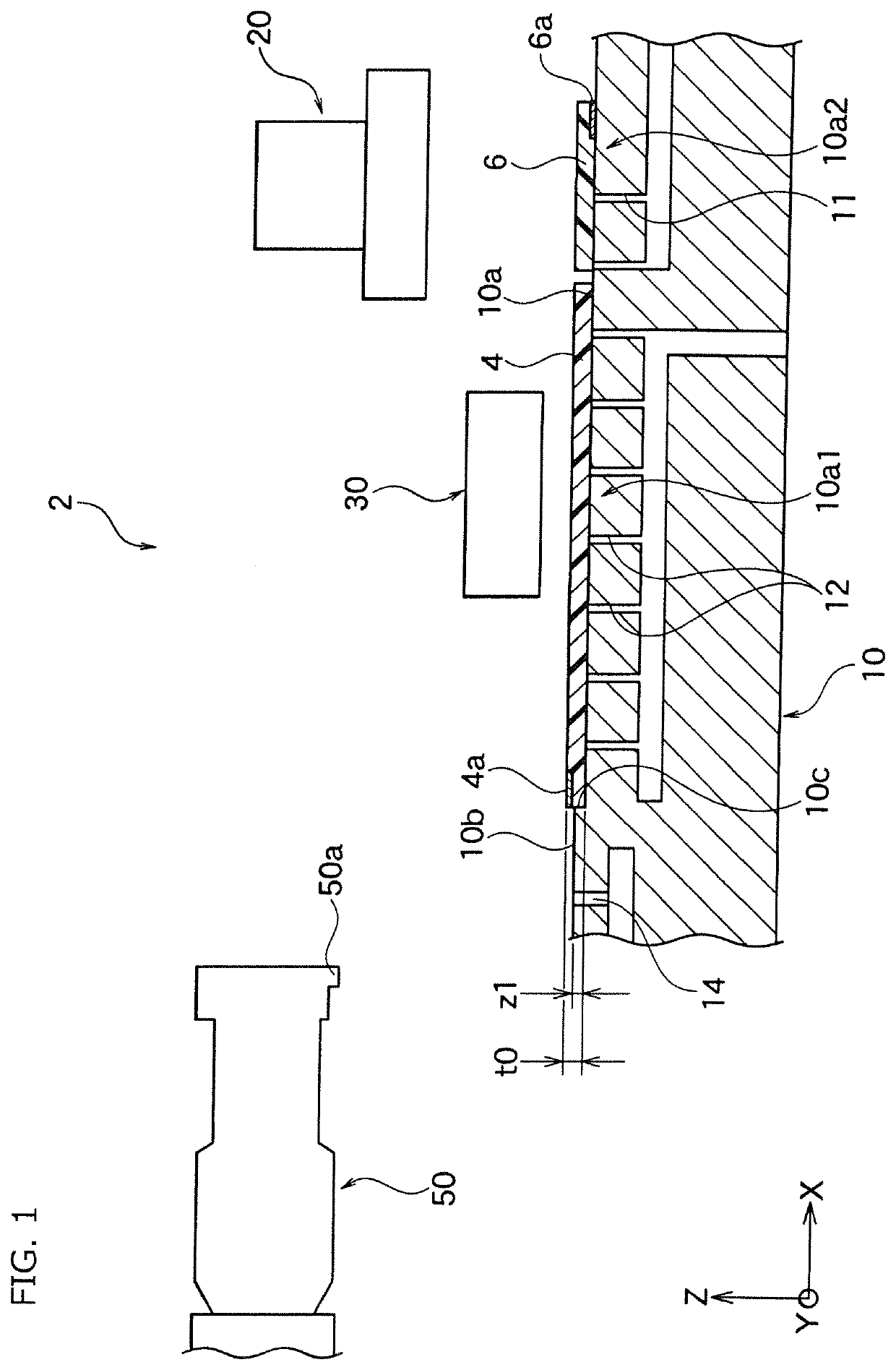
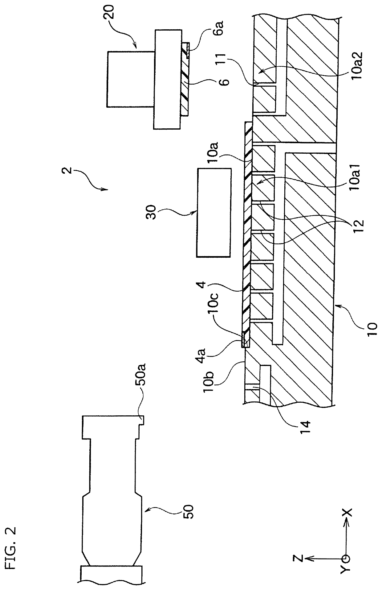
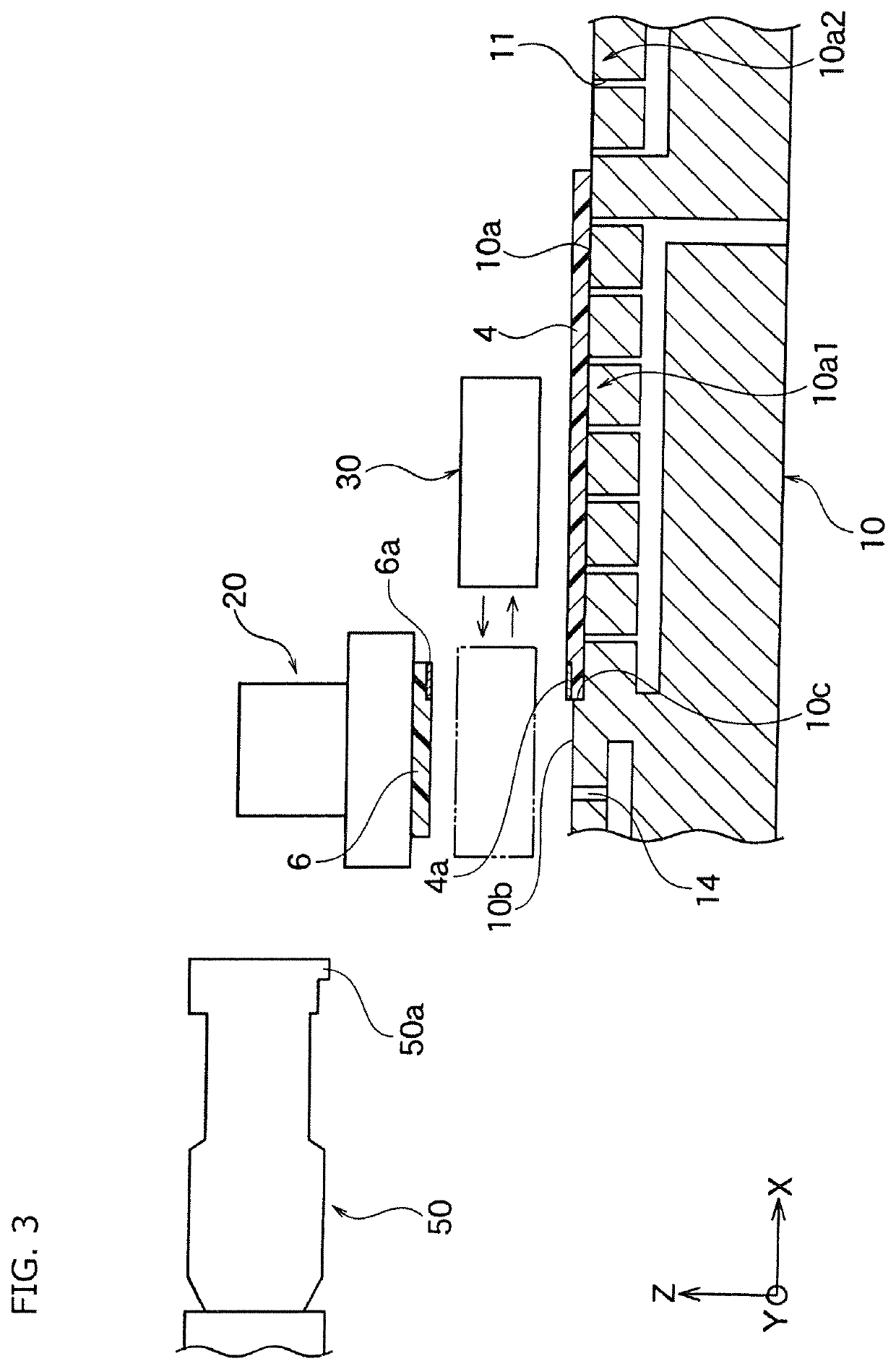
[0040]Described is a manner of manufacturing a board bonded body 8 shown in FIG. 5B by an ultrasonic bonding method shown in FIG. 2 to FIG. 5B using an ultrasonic bonding device 2 according to an embodiment of the present invention shown in FIG. 1.

[0041]As shown in FIG. 5B, the board bonded body 8 includes an electronic control board 4 (first flat member) and a flexible board 6 (second flat member). The electronic control board 4 may be a liquid crystal display panel, an organic EL display panel, or another display panel and may include, for example, a glass board.

[0042]The flexible board 6 is a board for supplying any signal and electric power to the electronic control board 4. A wiring pattern 4a of the electronic control board 4 and a wiring pattern 6a of the flexible board 6 are electrically connected to each other per pattern.

[0043]In the board bonded body 8 shown in FIG. 5B, after...


PUM

PropertyMeasurementUnit
widthaaaaaaaaaa
widthaaaaaaaaaa
widthaaaaaaaaaa

Abstract

An ultrasonic bonding device includes a stage and an ultrasonic horn. A first flat member and a second flat member to be bonded are placed on the stage. The ultrasonic horn includes a press part to be pressed on a laminated portion of the first flat member and the second flat member. The stage includes a lower-side surface, a higher-side surface, and a step wall surface. The first flat member is to be placed on the lower-side surface. The higher-side surface is positioned higher than the lower-side surface by a predetermined step height. The second flat member is to be placed on the higher-side surface. The step wall surface is positioned in a boundary between the lower-side surface and the higher-side surface.

Description

BACKGROUND OF THE INVENTION[0001]The present invention relates to an ultrasonic bonding device and to an ultrasonic bonding method.[0002]For example, as shown in Patent Document 1, known is a technique of connecting a wiring of a glass board to be a display screen board with a flexible printed circuit (FPC) or so via an anisotropic conductive film (hereinafter, ACF).[0003]In recent years, however, a pitch interval of wiring patterns has been smaller, and a short-circuit failure between wirings has been becoming a problem in connection by ACF.[0004]Patent Document 1: JP2016186517 (A)BRIEF SUMMARY OF INVENTION[0005]The present invention has been achieved under such circumstances. It is an object of the invention to provide an ultrasonic bonding device and an ultrasonic bonding method capable of easily electrically connecting flat members without generation of short-circuit failure or so even if a wiring pitch interval is small.[0006]To achieve the above object, an ultrasonic bonding d...

Claims


Application Information

Patent Timeline
Patent Type & Authority Applications(United States)
IPC IPC(8): B23K20/00G02F1/1345
CPCG02F1/1345B23K20/002H01L24/74H01L24/80H01L21/67092H01L21/607B23K20/10G02F1/13452G02F1/1303H05K3/323B23K2101/42B23K2103/54H05K13/00H05K3/361H01L24/75
Inventor SUNAGA, SEIJIROMIYAGOSHI, TOSHINOBUMAKIDA, MITSUYOSHI
Owner TDK CORPARATION
Why Eureka
Try Eureka