Electrical vertical take-off and landing aircraft

a vertical take-off and landing aircraft technology, applied in the field of airborne and flying vehicles, can solve the problems of compromising safety in built-up areas, unable to compete with similar payload-class, propeller-driven aircraft in speed and range, and current rotary-wing vtols, except for very advanced tilt rotor aircraft, to achieve the effect of simple, reliable and cost-effective design, and simple and cost-effective design

Inactive Publication Date: 2019-12-12
PFAMMATTER THOMAS +1
View PDF0 Cites 21 Cited by
  • Summary
  • Abstract
  • Description
  • Claims
  • Application Information

AI Technical Summary

Benefits of technology

[0020]The VTOL aircraft according to the invention provides a much simpler and cost-effective solution than the VTOLs aircraft known from the prior art as it relies essentially on electrically powered tiltable propellers associated with an inventive air-blowing steering system at the tail of the aircraft to provide any necessary steering and/or control of the aircraft during stationary hovering phases, vertical take-off and landing phases as well as

Problems solved by technology

Further, current rotary-wing VTOLs, except for very advanced tilt rotor aircraft, cannot compete with similar payload-class, fixed-wing, propeller-driven aircraft in speed and range when unrestricted expansive take-off and landing facilities and climb corridors are conveniently available at both ends of a mission.
To the degree that popular descriptions are accurate: (1) the configuration is a low aspect ratio tilt-wing, not a tilt-propeller; (2) the batteries in the FALX AIR are supplemental to the internal combustion engine to assist Hover-Out-of-Ground-Effect (HOGE) and climb and do not provide separate full HOGE power; hence, the FALX AIR lacks fully redundant power in the dead man zone for silent, safe take-of

Method used


Image

  • Electrical vertical take-off and landing aircraft
  • Electrical vertical take-off and landing aircraft
  • Electrical vertical take-off and landing aircraft

Examples


Embodiment Construction

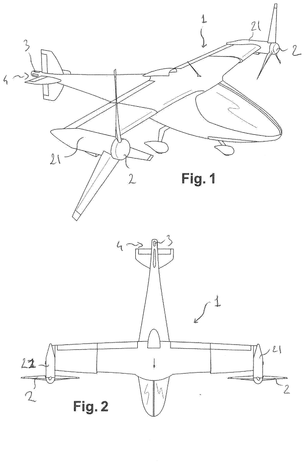
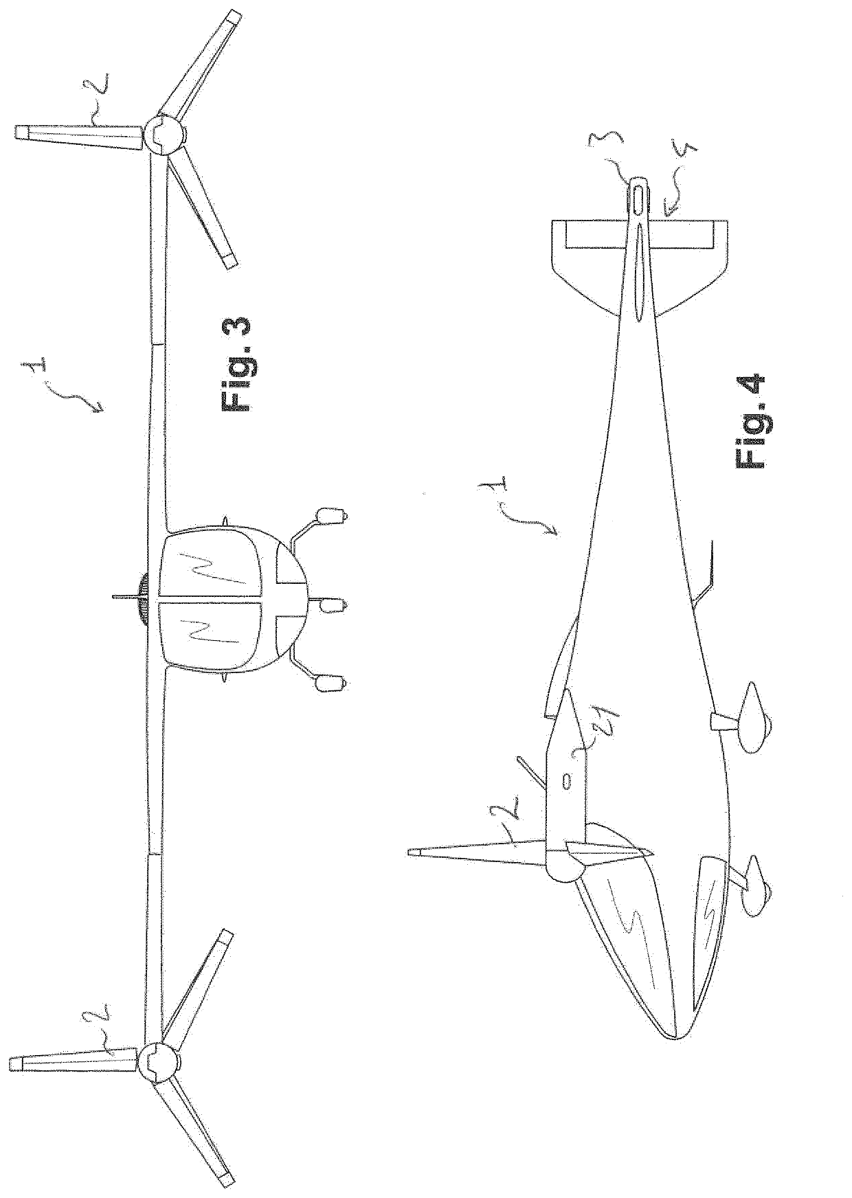
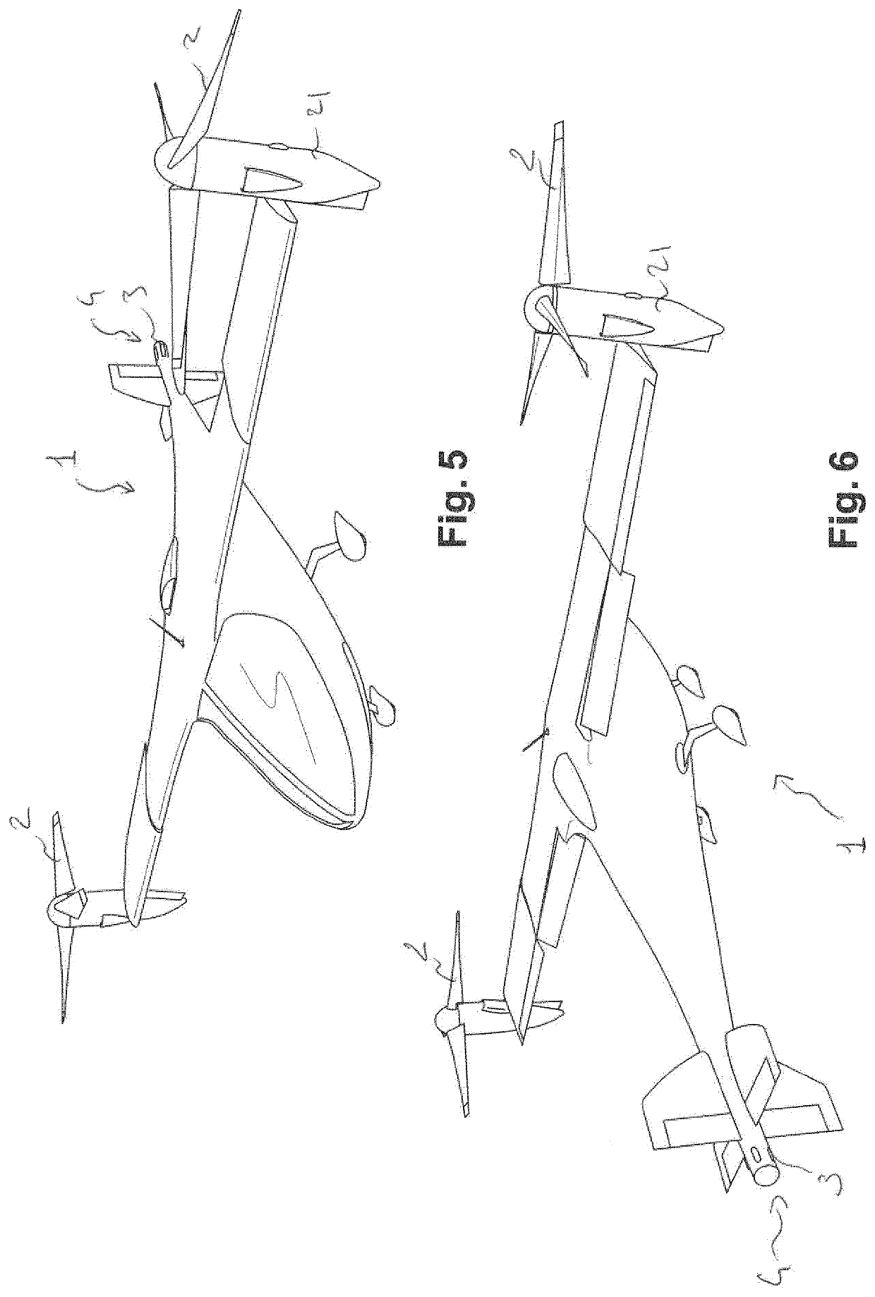
[0042]The present invention pertains to an electrically driven VTOL tilt-propeller aircraft 1, which may be described and referred to in the following description under the acronym E-VTOL.

[0043]The E-VTOL aircraft 1 of the invention, an example of which is represented in the appended figures, exploits advanced electric propulsion technology together with highly efficient, autonomously piloted Vertical Take-Off and Landing (VTOL) systems with pilot override. The E-VTOL aircraft 1 of the invention has been developed by the inventors with the aim of bringing the VTOL capable aircraft to a completely new status and commercial relevance and viability thanks to a tilt-propeller design relying on electrical power as energy for driving tiltable propeller units. The E-VTOL aircraft 1 of the invention accordingly offers a safe, legal, and practical flying vehicle to operate within populated, built-up localities, and to achieve speeds and ranges competitive with current fixed wing, propeller-d...


PUM


Abstract

Electrically powered Vertical Take-off and Landing (VTOL) aircraft are presented. Contemplated VTOL aircraft can include one or more electrical energy stores capable of delivering electrical power to one or more electric motors disposed within one or more propeller housings, where the motors can drive the propellers. The VTOL aircraft can also include one or more back-up and/or secondary energy/power sources (e.g., batteries, engines, generators, fuel-cells, semi-cells, etc.) capable of driving the motors should the energy stores fail or deplete. The VTOL aircraft will be significantly different to regular Tiltrotor aircraft as we use propellers and a modern steering system that reduces complicity dramatically. The contemplated configurations address safety, noise, and hover stability and outwash concerns to allow such designs to operate in built-up areas while retaining competitive performance relative to existing aircraft.

Description

TECHNICAL FIELD[0001]The present invention relates to the field of airborne and flying vehicles. More specifically it relates to an electrically powered aircraft having vertical take-off and landing as well as stationary flight capabilities.BACKGROUND[0002]Currently available vertically capable aircraft, also known as vertical take-off and landing (VTOL) aircraft are generally denied permission for routine powered terminal operations (e.g. take-off, low altitude climb, landing, etc.) in populated, built-up areas for one or more of four reasons: safety, noise, exhaust emissions, or outwash velocity. Further, current rotary-wing VTOLs, except for very advanced tilt rotor aircraft, cannot compete with similar payload-class, fixed-wing, propeller-driven aircraft in speed and range when unrestricted expansive take-off and landing facilities and climb corridors are conveniently available at both ends of a mission. So the simultaneous attainment of radically improved terminal safety, toler...

Claims


Application Information

Patent Timeline
IPC IPC(8): B64C27/26B64C27/28
CPCB64C27/28B64C29/0033B64D2221/00B64D27/14B64C2027/8245B64C27/26B64D2027/026B64C29/0083
Inventor PFAMMATTER, THOMASSTEFFEN, DOMINIQUEDEMONT, SÉBASTIEN
Owner PFAMMATTER THOMAS
Why Eureka
Try Eureka