Hybrid inertial measurement system and method using a light pulse cold atom interferometer

a cold atom accelerometer and hybrid technology, applied in the field ofinertial measurement instruments, can solve the problems of limiting the robustness of the atomic interferometer to tilt and vibration, the bulky and heavy system the different factors that limit mainly the operation and the performance of the cold atom accelerometer, so as to avoid the loss of the sensing effect of measuremen

Active Publication Date: 2019-12-12
EXAIL +3
View PDF0 Cites 14 Cited by
  • Summary
  • Abstract
  • Description
  • Claims
  • Application Information

AI Technical Summary

Benefits of technology

[0022]Said system makes it possible to correct the laser frequency and not only the phase thereof. Moreover, the correction is performed in real time during the measurement of the cold atom interferometric sensor and not between two interferometric measurements.
[0023]Said system also makes it possible to compensate in real time for the continuous and/or frequency modulation accelerations of the reference frame with reference to the cold atoms, due for example to the movement of the vehicle in which the inertial system is integrated. Hence, said system makes it possible to avoid a loss of sensibility of the measurement due to the m

Problems solved by technology

However, these atomic interferometry systems are confronted with limits in terms of robustness to tilts and vibrations.
Most of the cold atom accelerometers are bulky and heavy systems adapted to operate in a controlled laboratory environment and in a limited range of acceleration.
In the mobile applications, for example inertial navigation, different factors limit mainly the operation and the performances of the cold atom accelerometers.
Firstly, the interferometer no longer operates when its orientation varies randomly or when its movements are random.
Indeed, the movements of the inertial system harm the stability of the reflective surface.
On the other hand, a misalignment between the normal to the mirror and the local vertical axis introduces a systematic measure

Method used


Image

  • Hybrid inertial measurement system and method using a light pulse cold atom interferometer
  • Hybrid inertial measurement system and method using a light pulse cold atom interferometer
  • Hybrid inertial measurement system and method using a light pulse cold atom interferometer

Examples


Embodiment Construction

[0046]The following description in relation with the appended drawings, given by way of non-limitative example, will allow a good understanding of what the invention consists of and of how it can be implemented.

[0047]In the appended drawings:

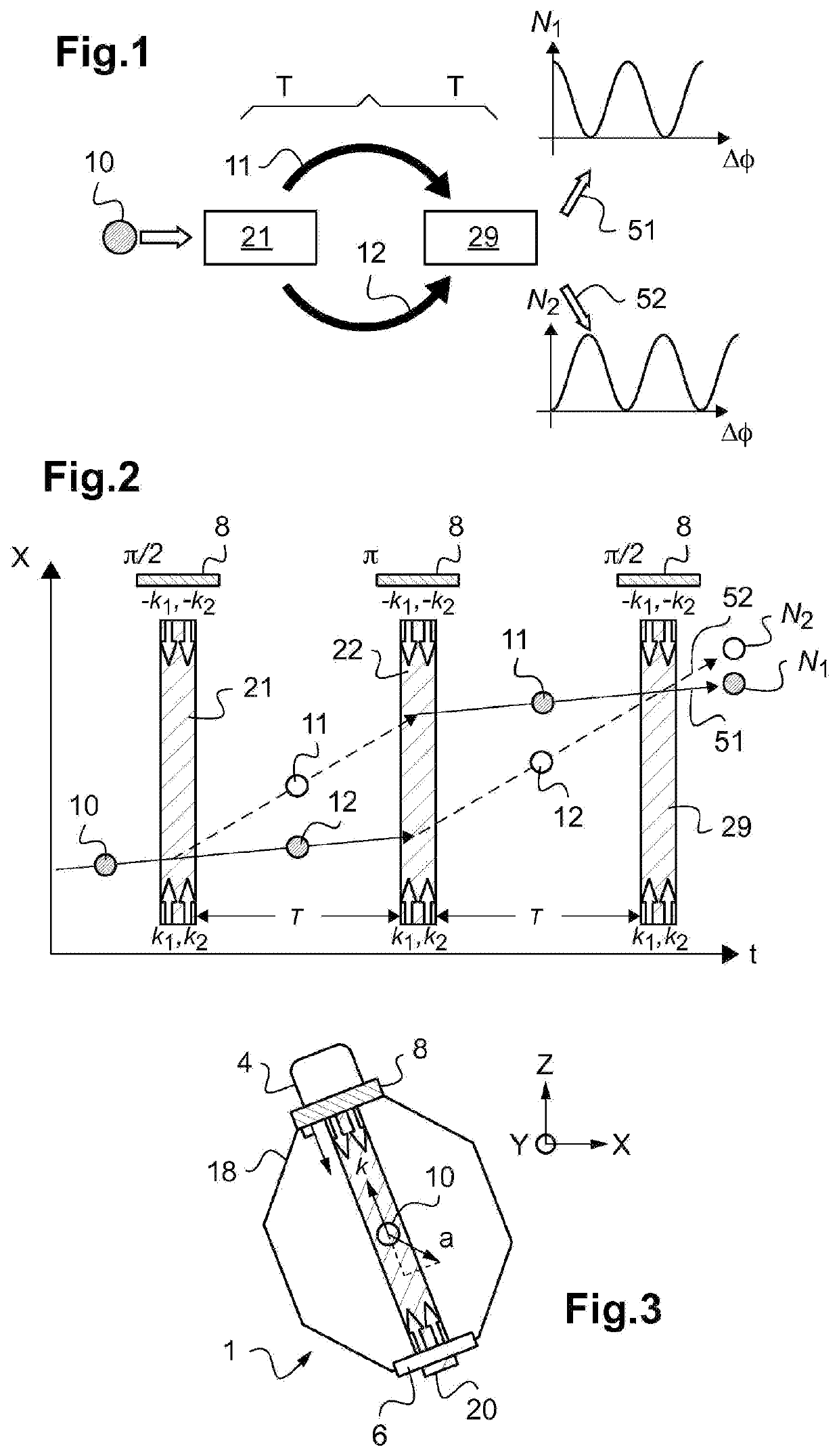
[0048]FIG. 1 schematically shows the principle of a cold atom interferometer;

[0049]FIG. 2 schematically shows a cold atom interferometer in Mach-Zehnder configuration;

[0050]FIG. 3 shows an example of cold atom accelerometer;

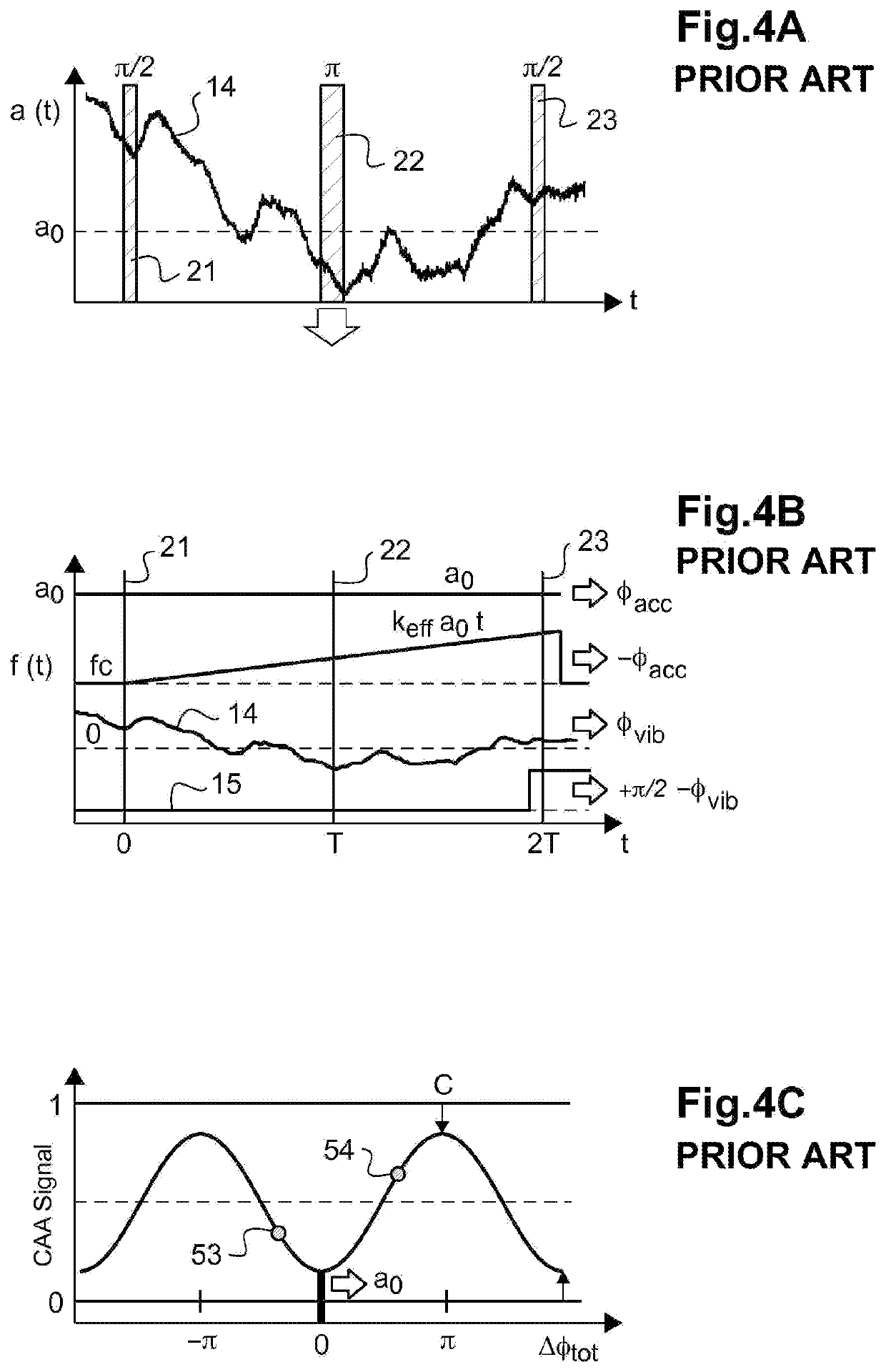
[0051]FIG. 4 illustrates acceleration measurements in a cold atom interferometer with pre-compensation for a constant acceleration between the reference of the frame and the cold atoms and a real time compensation for the phase;

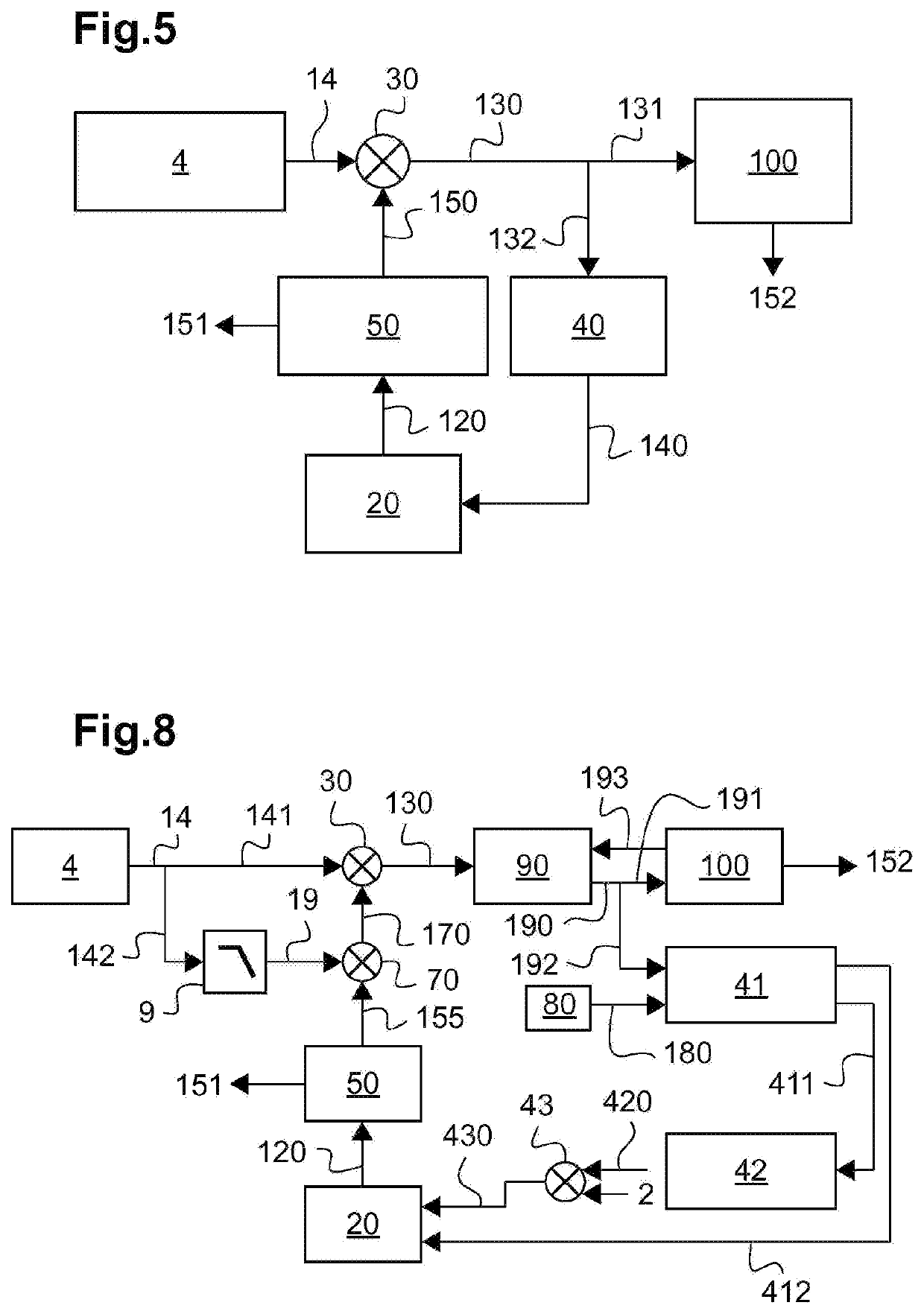
[0052]FIG. 5 schematically shows a hybrid, dual feedback loop measurement system for correcting in real time the measurements of a conventional inertial sensor by means of the signal of a cold atom inertial sensor;

[0053]FIG. 6 schematically shows a variant of a feedback loop measurement system for corr...


PUM


Abstract

Disclosed is a hybrid inertial measurement system including a cold atom interferometric inertial sensor having a laser source generating a sequence of laser pulses towards a cold atom burst and a conventional inertial sensor attached to the inertial reference frame of the interferometric inertial sensor. The hybrid system includes a signal processing system suitable for receiving an inertial measurement signal from the conventional inertial sensor and for generating in real time a non-linear frequency modulation signal, the feedback loop electronic system being configured to modulate in real time the central optical frequency of the laser according to the modulation signal, such that the cold atom interferometric inertial sensor generates a first hybrid inertial measurement signal by atomic interferometry corrected for the relative movements of the inertial reference frame.

Description

TECHNICAL FIELD TO WHICH THE INVENTION RELATES[0001]The present invention generally relates to the field of inertial measurement instruments for measuring a local speed of rotation or acceleration due, for example, to gravity.[0002]It more particularly relates to inertial measurement instrument and method based on the use of a cold atom interferometer for very accurate measurements.[0003]It more particularly relates to an inertial acceleration, gravity and / or rotation sensor based, in particular, on an atomic interferometer.TECHNOLOGICAL BACK-GROUND[0004]The inertial sensors based on the atomic interferometry provide a great sensitivity and find applications in inertial navigation, seismology or geophysics, to locally measure gravity.[0005]For about twenty years, the atomic interferometry techniques have allowed the development of new measurement instruments, for example gravimeters, gradiometer, accelerometers, gyroscopes, atomic clocks and electromagnetic field sensors.[0006]An at...

Claims


Application Information

Patent Timeline
IPC IPC(8): G01C19/58G01P15/093
CPCG01C19/58G01P15/093G01P15/08G01C21/165G01C19/64G01C21/16
Inventor BARRETT, BRYNLEBATTELIER, BAPTISTEBOUYER, PHILIPPENAPOLITANO, FABIEN
Owner EXAIL
Why Eureka
Try Eureka