Supercharge Your Innovation With Domain-Expert AI Agents!

Electric park lock actuator limited rotary disconnect

a technology of electric park lock and actuator, which is applied in the direction of mechanical equipment, braking systems, transportation and packaging, etc., can solve the problems of reducing accuracy, affecting the operation of electric motors with lower cogging torque, and changing mechanical design, etc., to achieve the effect of higher gear ratio

Active Publication Date: 2019-12-19
VITESCO TECH USA LLC
View PDF0 Cites 5 Cited by
  • Summary
  • Abstract
  • Description
  • Claims
  • Application Information

AI Technical Summary

Benefits of technology

The present invention is an electronic park lock actuator (also known as an electronic parking pawl actuator) that uses a smaller, higher cogging torque motor with a higher gear ratio, which prevents the actuator from being back driven beyond its range. This makes it possible to reach park detents with a smaller motor and higher gear ratio, reducing mechanical and software design complexity. The actuator also limits the amount of back drivable range for theft deterrence and allows operation and a lower motor peak current. The actuator has a slot designed into it to achieve its lowest energy position, and a drive mechanism that is engaged with a detent selector of a transmission, allowing the detent selector to be in a desired position. A first and second spring is in contact with the worm gear and the gear selector linkage component, which increases the amount of rotational force applied to the drive mechanism as the gear selector linkage component changes position. The compressive force in the springs is reduced once the gear selector linkage component is positioned such that the transmission is configured to operate in the desired gear.

Problems solved by technology

However, the changes to the mechanical design add additional cost beyond the current existing design.
With wear and tear, accuracy diminishes, which requires greater base accuracy to account for this reduction over time.
Current attempts to allow for position control at the rooster comb result in larger electric motors with lower cogging torque and lower gear ratios, adding additional expense.

Method used


Image

  • Electric park lock actuator limited rotary disconnect
  • Electric park lock actuator limited rotary disconnect
  • Electric park lock actuator limited rotary disconnect

Examples


first embodiment

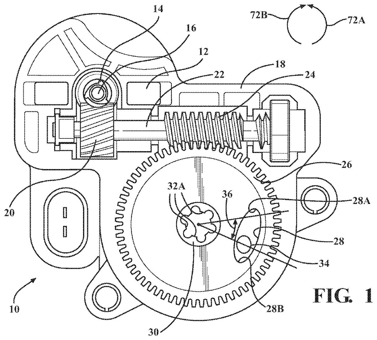
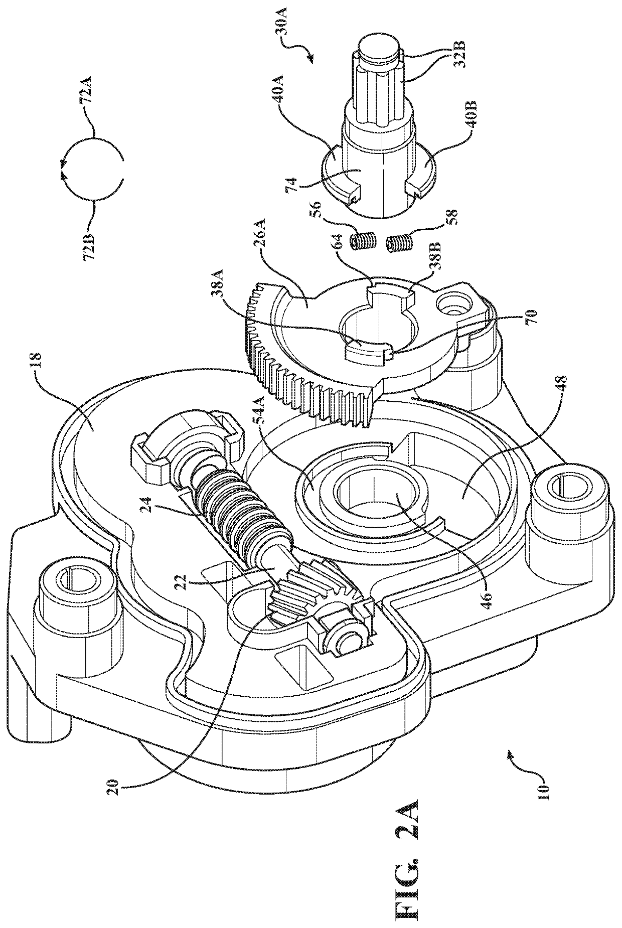
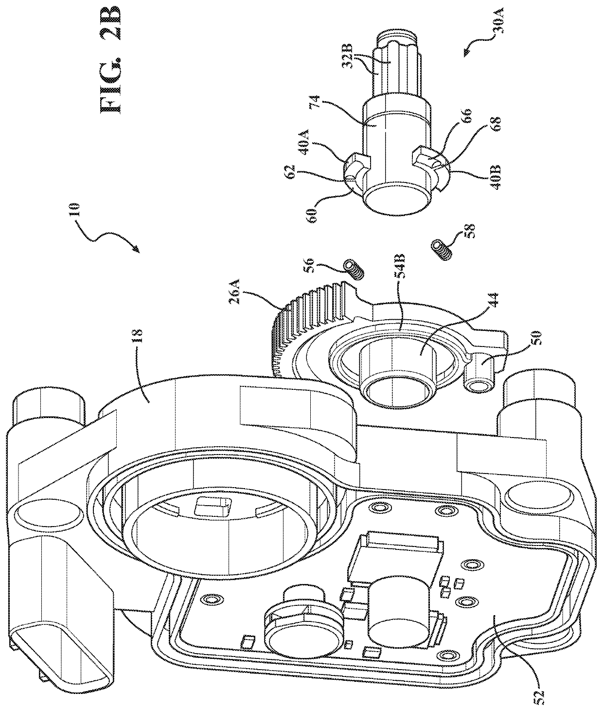
[0047]an electronic parking pawl actuator according to the present invention is shown in FIG. 1, generally at 10. The actuator 10 includes an electric motor 12 having a worm gear 14 mounted on a shaft 16. The motor 12 is connected to a housing 18 such that the shaft 16 extends through the housing 18.

[0048]The worm gear 14 is in mesh with a worm gear 20, and the worm gear 20 is mounted on a shaft 22. Formed as part of the shaft 22 is a second-stage worm gear 24, and the second-stage worm gear 24 is in mesh with another second-stage worm gear 26. Integrally formed with the second-stage worm gear 26 is a pin 34, which is used to couple the second-stage worm gear 26 to a drive mechanism 30 having a spline joint 32A, where the spline joint 32A is integrally formed as part of an output shaft (not shown in FIG. 1).

[0049]The spline joint 32A of the drive mechanism 30 is connected to a corresponding spline joint of an output shaft of a detent selector, or “rooster comb,” inside the transmiss...


PUM


Abstract

An electronic parking pawl actuator which uses a smaller motor and higher gear ratio has the ability to configure a rooster comb to engage with various park detents, and reduces the mechanical and software design complexity. Furthermore, the electronic park actuator limits the amount of back drivable range (unable to perform an external park to neutral shift) for theft deterrence, and also allows operation (speed performance) and a lower motor peak current. The electronic parking pawl actuator includes an electric motor, a drive gear, the drive gear operable for being driven by the electric motor, and a drive mechanism, the drive mechanism is operable for being driven by the drive gear. The drive mechanism is engaged with an output shaft of a gear selector of a transmission, and the drive mechanism is rotatable relative to the drive gear, allowing the output shaft to be located in a desired position.

Description

CROSS-REFERENCE TO RELATED APPLICATIONS[0001]This application claims the benefit of provisional application 62 / 684,577, filed Jun. 13, 2018. The disclosure of the above application is incorporated herein by reference.FIELD OF THE INVENTION[0002]The invention relates generally to an electronic parking pawl actuator which has the ability to configure a rooster comb to engage with various park detents using a smaller motor and higher gear ratio, and reduces the mechanical and software design complexity.BACKGROUND OF THE INVENTION[0003]Most transmissions in motor vehicles have a parking pawl to lock the transmission to prevent roll on a grade or when parked. This parking pawl meshes with teeth on a gear in the transmission, preventing rotation. The parking pawl is actuated by a spring-loaded actuator rod coupled through a so-called rooster comb. The rooster comb is a plate with multiple peaks and troughs, or detents. A spring-loaded follower falls into these detents to identify the gear...

Claims


Application Information

Patent Timeline
IPC IPC(8): F16H63/34B60T1/00
CPCF16H63/3466F16H63/3416B60T1/005B60T13/745B60T1/062F16D63/006F16D2121/24F16D2125/52F16H63/3425F16H2063/3066
Inventor MERWIN, JEFFREY D.RODRIGUES, KEITH JOSEPHHRIBAR, EDWARD
Owner VITESCO TECH USA LLC
Features
  • R&D
  • Intellectual Property
  • Life Sciences
  • Materials
  • Tech Scout
  • Unparalleled Data Quality
  • Higher Quality Content
  • 60% Fewer Hallucinations
Learn More