Pellet stove

a pellet stove and pellet technology, applied in the field of pellet stoves, can solve the problems of pellets smoldering and smoke, pellets may eventually be extinguished, temperature drop, etc., and achieve the effects of reducing pollutants, improving the efficiency of pellet stoves, and controlling the burn rate of pellets

Active Publication Date: 2019-12-19
HILL RICHARD L +1
View PDF0 Cites 3 Cited by
  • Summary
  • Abstract
  • Description
  • Claims
  • Application Information

AI Technical Summary

Benefits of technology

[0023]The present invention therefore has a primary object of providing a pellet stove in which the burn rate of the pellets can be controlled.
[0024]The invention has the further object of improving the efficiency of a pellet stove.
[0025]The invention has the further object of providing a pellet stove having reduced emissions of pollutants.
[0026]The invention has the further object of reducing the amount of maintenance required in a pellet stove.
[0027]The invention has the further object of providing a pellet stove which can work well at various altitudes.

Problems solved by technology

If insufficient air is passed over the burning pellets, the burn temperature drops, the pellets smolder and smoke, and the pellets may eventually be extinguished.
The U.S. Environmental Protection Agency (EPA) has issued new regulations for wood burning stoves, and many existing wood burning stoves will not comply with the new regulations.
In addition, many local government entities are trying to reduce dramatically the number of wood stoves due to pollution concerns.
Powered pellet stoves have several disadvantages, as compared with gravity-fed systems, including the noise of the fan and auger motor, the cost of replacement parts, down time to replace components, and the inability to work during power outages.
The low air movement of the natural draft is very fragile and it is easy to interrupt the draft, causing the pellets to smoke, smolder, and become extinguished.
This creates challenges for doing a controlled and sustained low heat burn.
Using spacing to regulate how fast the pellets move through the primary burn chamber creates several challenges.
A first challenge is that a stove that is calibrated with primary burn chamber spacing set to burn and drop a given amount of pellets to reach a given temperature on a high temperature burn at sea level will lose about 100 degrees of heat exhaust output when the same stove is moved to a 5,000 foot elevation.
Also, such stove will burn much cooler due to the fact that there is less oxygen in the air.
This backup of unburned pellets restricts the draft and / or plugs up the stove, so that the pellets begin to smoke, smolder, and eventually become extinguished.
If larger holes and / or slots are cut in the secondary burn plate, the pellets do not finish burning before dropping into the ash pan.
An additional challenge comes from where the manufacturers of many natural draft gravity-fed stoves locate the secondary burn plate.
This causes the pellets to burn more slowly, spending more time on the secondary burn plate.
More time spent on the secondary burn plate contributes to pellet buildup which contributes to restricting the draft and / or clogging the stove, causing the pellets to smoke, smolder, and become extinguished.

Method used


Image

  • Pellet stove
  • Pellet stove
  • Pellet stove

Examples


first embodiment

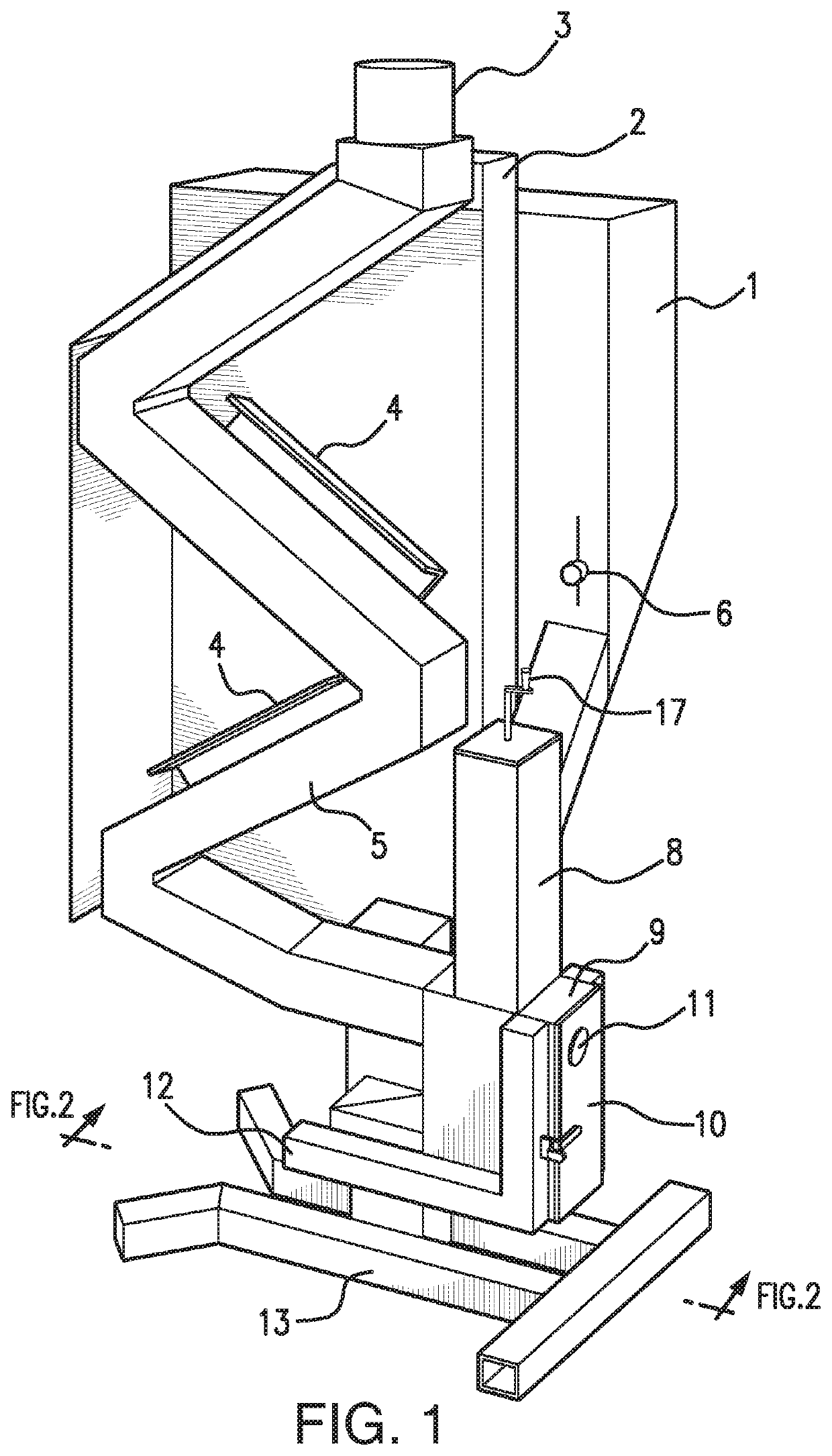
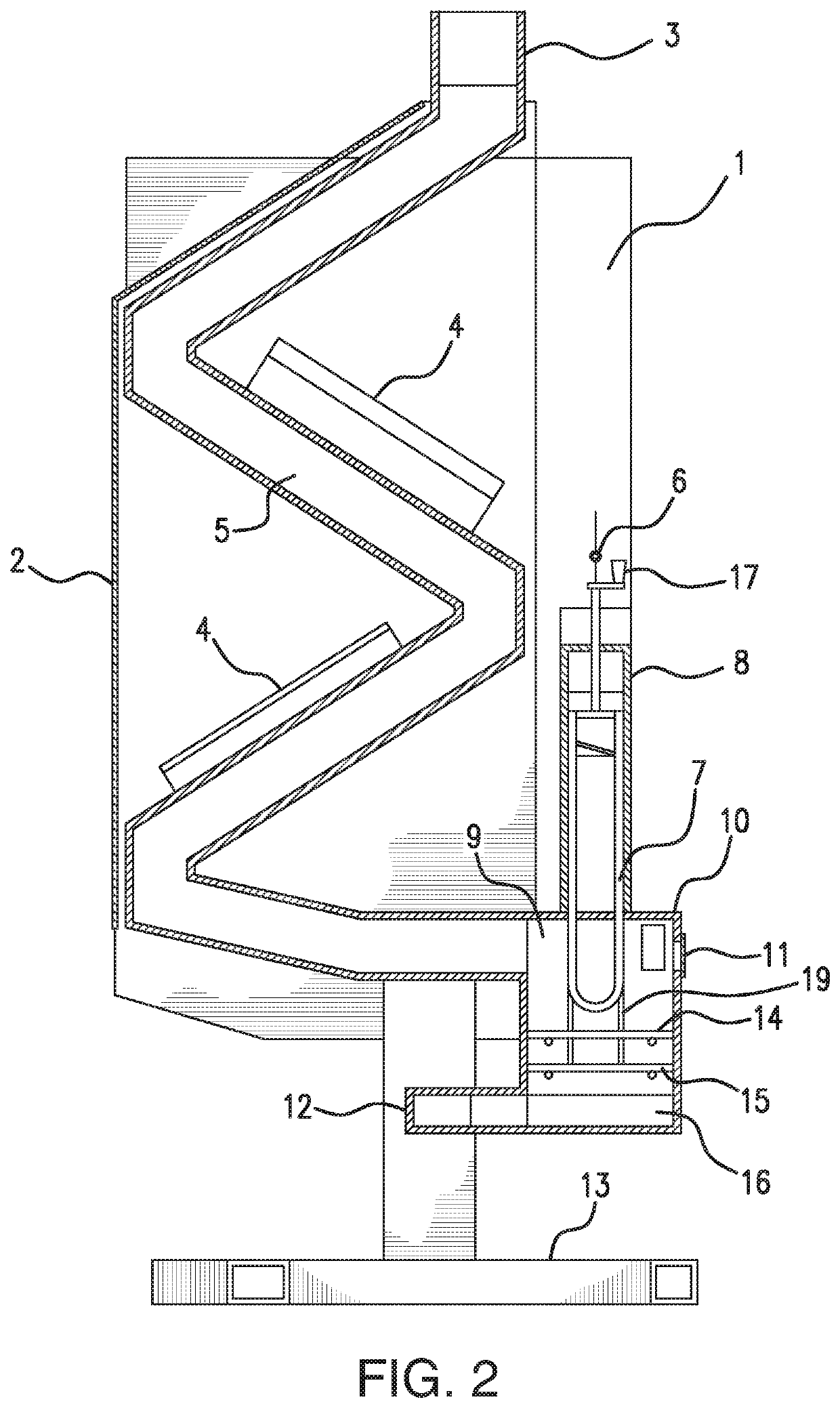
[0086]The pellet stove includes exhaust or heat tube 27, and air deflectors 28 positioned along segments of the heat tube. The heat tube terminates at chimney connector 29, which connects to a chimney (not shown) or other means for disposing of exhaust gas. Support leg 30 for the burn chamber includes an air inlet 31, similar to that of the Basket adjuster 32 controls the position of the basket, in a manner to be described later.

[0087]In the embodiment of FIGS. 4-7, the top section 33 of the heat tube is horizontal, i.e. parallel to the floor, and not at an angle, as was the case in the first embodiment. This feature allows the operator to use this flat area to heat coffee, water, and food. A heat shield can be provided along the top section 33, and such heat shield could be hinged, allowing it to be in place, close to the top section 33, during normal use, and to be swung upward and out of the way when the top section is being used for heating food and the like.

[0088]The exploded ...

second embodiment

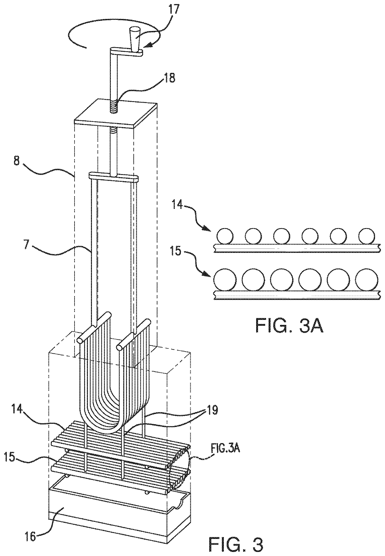
[0095]FIGS. 5 and 6 illustrate the control of the position of the basket in the Basket 36 is attached to control arm 47. The control arm is engaged by threaded portion 48 connected to basket adjuster 32. The adjuster 32 is turned as indicated by arrow 49 in FIG. 6. Turning the adjuster 32 thereby causes the basket to rotate, in either of the directions indicated by arrow 50. The positions shown in FIGS. 5 and 6 show the extreme positions of the basket. In the position shown in FIG. 5, the basket has been rotated such that it has been moved generally farther from the floor. When the basket is raised up in this position, fewer pellets are allowed in the basket for a lower temperature burn. In the position shown in FIG. 6, the contents of the basket are closer to the floor. When the basket is lowered in this position, more pellets are allowed in the basket for a higher temperature burn. Thus, the movements of the basket, shown in FIGS. 5 and 6, change the amount of pellets allowed in ...


PUM


Abstract

A pellet stove includes a hopper for storing pellets, a basket for receiving the pellets by gravity, a duct for conveying combustion air to the basket, and a conduit for conducting heated air away from the basket. The position of the basket is adjustable, such as by raising and lowering it, or by rotating it, so as to control the number of pellets in the area of most intense combustion. One or more optional burn plates, positioned below the basket, provide platforms on which pellets falling through the basket can burn down to a smaller size. The pellet stove requires no external source of power. The stove so constructed enables quiet, efficient and clean burning of the pellets.

Description

CROSS-REFERENCE TO RELATED APPLICATIONS[0001]This is a continuation-in-part of U.S. patent application Ser. No. 15 / 729,723, filed Oct. 11, 2017, which is a continuation of U.S. patent application Ser. No. 14 / 955,189, filed Dec. 1, 2015, which claims the priority of U.S. Provisional Patent Application Ser. No. 62 / 088,366, filed Dec. 5, 2014, the entire disclosure of which is hereby incorporated by reference.FIELD OF THE INVENTION[0002]The present invention relates to pellet stoves and the like.BACKGROUND OF THE INVENTION[0003]Pellet stoves are operated in many domestic, commercial, and industrial premises as a heating source. Pellet stoves burn fuel in the form of pellets. The pellets are made of ground up wood, which is dried to a low moisture content (approximately 8%), and then pressed into pellet shapes. The pellets are typically approximately 0.25 inches in diameter, and may range up to about one inch long, though other pellet sizes are possible. The pressing process creates hea...

Claims


Application Information

Patent Timeline
Patent Type & Authority Applications(United States)
IPC IPC(8): F24B13/04F23B50/00F24B1/02F23B50/12F23B60/02F23H1/06F23H17/06F23J1/00F24B13/02
CPCF23H1/06F23B50/00F23B60/02F24B13/04F23H17/06F24B13/02F23J1/00F24B1/024F23B50/12F23B30/02F23B50/02F24B1/08F24B1/028Y02B40/00
Inventor HILL, RICHARD L.ALEXANDER, DON P.
Owner HILL RICHARD L
Why Eureka
Try Eureka