Vehicle stabilizer and method of manufacturing the same

a technology of stabilizer and stabilizer plate, which is applied in the direction of mechanical equipment, transportation and packaging, and torsion springs, etc., can solve the problems of affecting the stability of the vehicle, and generating noise, so as to prevent axial displacement

Active Publication Date: 2020-01-09
NHK SPRING CO LTD
View PDF0 Cites 0 Cited by
  • Summary
  • Abstract
  • Description
  • Claims
  • Application Information

AI Technical Summary

Benefits of technology

[0007]Embodiments described herein aim to provide a stabilizer comprising a restriction ring that can withstand a large component load and capable of preventing axial displacement, and a method of manufacturing the same.

Problems solved by technology

If the position of the stabilizer is shifted in the axial direction, the stabilizer interferes with the accessory of the vehicle to generate noise.
However, when the weight of the vehicle increases, the component load for moving the torsion portion in the axial direction increases.
If the restriction ring is applied to a stabilizer mounted on a large vehicle, the restriction ring cannot withstand the component load and may fall off.

Method used


Image

  • Vehicle stabilizer and method of manufacturing the same
  • Vehicle stabilizer and method of manufacturing the same
  • Vehicle stabilizer and method of manufacturing the same

Examples


Embodiment Construction

[0026]One of the embodiments of the present invention will be described hereinafter with reference to the accompanying drawings.

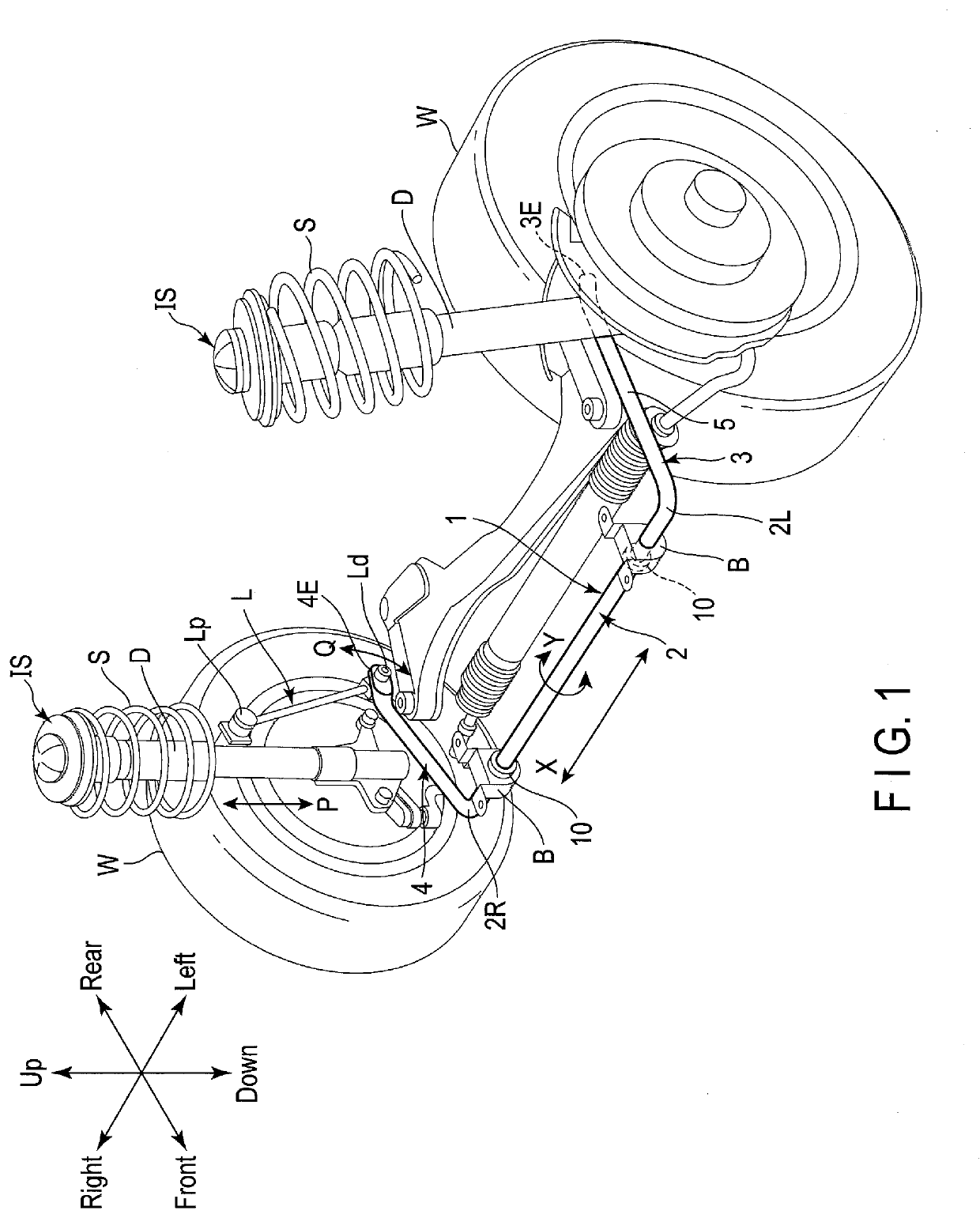
[0027]A stabilizer 1 according to one of embodiments of the present invention will be explained hereinafter with reference to FIG. 1 to FIG. 14. FIG. 1 is a perspective view showing an example of the stabilizer 1 in a state of being mounted on a vehicle. The stabilizer (stabilizer bar) 1 is formed by bending a bar of spring steel into a U-shape.

[0028]Examples of the steel type are, for example, SAE10B21, SAE15B26, SAE5160, etc., conforming to the regulations of the American Association of Automotive Engineers or, for example, SUP9, etc., conforming to JIS or, for example, 26MnB5, 34MnB5, etc. The steel type of the stabilizer 1 is not limited to only spring steel, but may be high strength steel or steel for carburization. The stabilizer 1 is covered with a coating film 5 such as an epoxy-based paint containing a corrosion-resistant component.

[0029]The stabil...


PUM


Abstract

A stabilizer is provided with a restriction ring connected to a torsion portion at a connection portion adjacent to a bush. The restriction ring has a body, a female portion, a male portion, and a welded portion. The female portion has gripping portions with a spacing therebetween decreasing in the direction away from a valley bottom portion. The male portion has a neck portion, an expansion portion, and a contraction portion. The welded portion covers at least the range of the contraction portion and the valley bottom portion and melts in the plate thickness direction from the outer peripheral surface.

Description

CROSS-REFERENCE TO RELATED APPLICATIONS[0001]This application is a Continuation Application of PCT Application No. PCT / JP2018 / 005521, filed Feb. 16, 2018 and based upon and claiming the benefit of priority from prior Japanese Patent Application No. 2017-051335, filed Mar. 16, 2017, the entire contents of all of which are incorporated herein by reference.BACKGROUND OF THE INVENTION1. Field of the Invention[0002]The present invention relates generally to a stabilizer for vehicle comprising a restriction ring that restricts movement in an axial direction, and a method of manufacturing the stabilizer.2. Description of the Related Art[0003]A vehicle such as an automobile comprises a stabilizer that interlocks suspension units of right and left wheels to suppress rolling of the vehicle body and improve traveling stability. The stabilizer is a rod member of spring steel bent in a U-letter shape, and comprises a torsion portion suspended from a bottom surface of the vehicle body via a cylin...

Claims


Application Information

Patent Timeline
Patent Type & Authority Applications(United States)
IPC IPC(8): B60G21/055F16B11/00
CPCB60G2204/1222B60G2206/8102F16B11/00B60G2206/8201B60G21/0551B60G2202/135B60G2204/41B60G2204/44B60G2206/427B60G2206/7102B60G2206/8208B60G2206/8209B60G2204/45F16F1/16B23K2101/006F16B11/002B60G21/055B60G2600/72
Inventor NAKAMURA, TAKAHIROKATSUNO, KENJI
Owner NHK SPRING CO LTD
Why Eureka
Try Eureka