

Determining method and control method for straight running of robot on slope plane
a technology of determining method and controlling method, which is applied in the field of robot applications, can solve the problems of affecting the efficiency of the solar panel directly absorbing sunlight, limiting photoelectric efficiency, and the work environment of the solar panel, and achieves the effect of high working efficiency
- Summary
- Abstract
- Description
- Claims
- Application Information
AI Technical Summary
Benefits of technology
Problems solved by technology
Method used
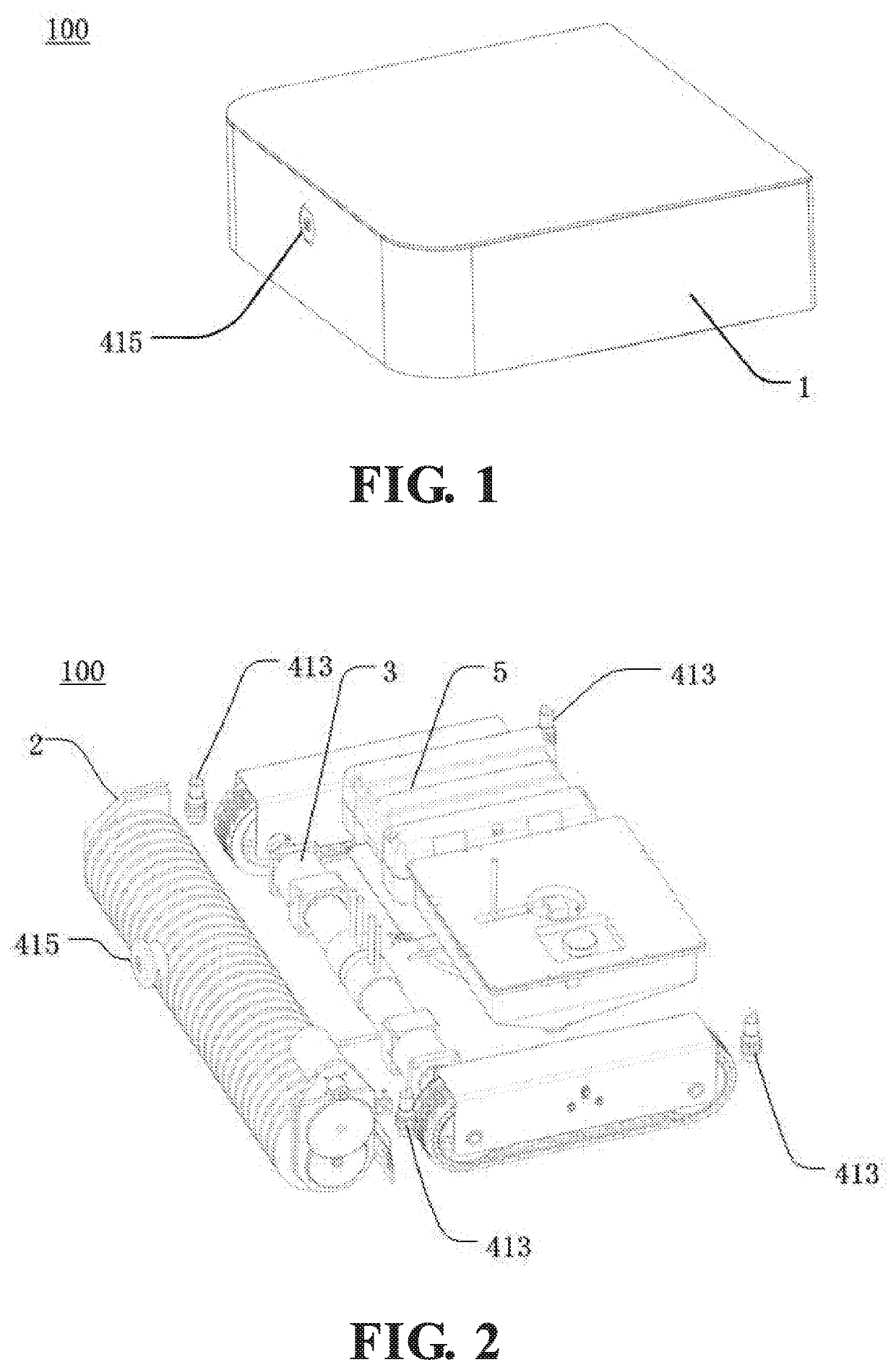
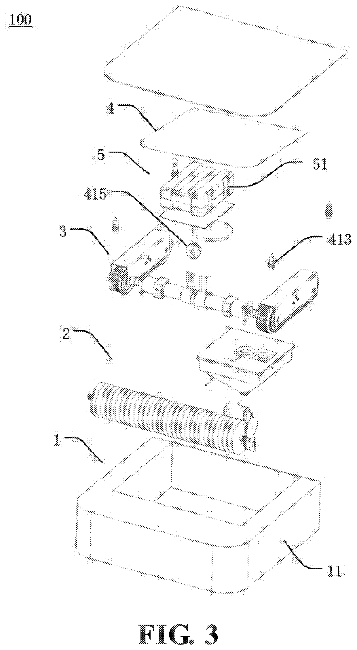
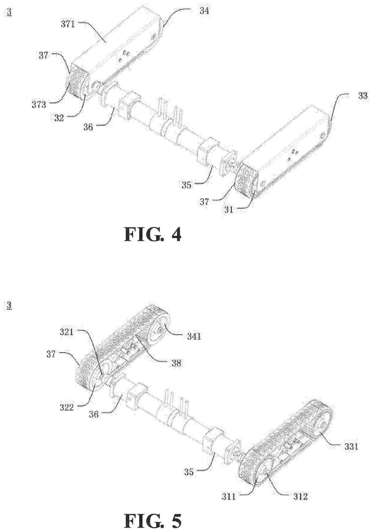
Image

Examples
first embodiment
[0088]path navigation method for the robot to move on a rectangular slope, disclosed in the present embodiment, includes steps as follows: step S101) including setting a left-lower corner of the rectangular slope as a navigation starting point; step S102) including controlling the robot to move straightly from the navigation starting point to a left-upper corner of the rectangular slope; step S103) including detecting in real-time whether the robot reaches a first corner of the rectangular slope, wherein if the robot does not reach the first corner, and the method returns to step S102), wherein if the robot reaches the first corner, controlling the robot to turn right 90 degrees is implemented; step S104) including controlling the robot to move straight; step S105) including detecting in real-time whether the robot reaches a second corner of the rectangular slope; if the robot does not reach the second corner, the method returns to step S104), wherein if the robot reaches the second...
second embodiment
[0090]the path navigation method for the robot to move on the rectangular slope, disclosed in the present embodiment, includes steps as follows: step S201) includes setting the right-lower corner of the rectangular slope as a navigation starting point; step S202) includes controlling the robot to move straightly from the navigation starting point to the right-upper corner of the rectangular slope; step S203) includes detecting in real-time whether the robot reaches the first corner of the rectangular slope, wherein if the robot does not reach the first corner, the method returns to step S202), wherein if the robot reaches the first corner, controlling the robot to turn left 90 degrees is implemented; step S204) includes controlling the robot to move straight; step S205) includes detecting in real-time whether the robot reaches the second corner of the rectangular slope, wherein if the robot does not reach the second corner, the method returns to step S204), wherein if the robot reac...
third embodiment
[0092]the path navigation method for the robot to move on the rectangular slope, disclosed in the present embodiment, includes steps as follows: step S301) includes setting the left-lower corner of the rectangular slope as a navigation starting point; step S302) includes controlling the robot to move straightly from the navigation starting point to the left-upper corner of the rectangular slope; step S303) including detecting in real-time whether the robot reaches the first corner of the rectangular slope, wherein if the robot does not reach the first corner, the method returns to step S302), wherein if the robot reaches the first corner, controlling the robot to implement a right U-turn is implemented; step S304) includes detecting in real-time whether the robot reaches the second corner of the rectangular slope, wherein if the robot does not reach the second corner, controlling the robot to move straightly is implemented, wherein if the robot reaches the second corner, controlling...
PUM
 Abstract
Description
Claims
Application Information