
Apparatus and methods for edge ring replacement, inspection and alignment using image sensors

an image sensor and apparatus technology, applied in the field of substrate processing systems and methods, can solve the problems of time-consuming process of replacing the damage edge ring, requiring replacement of the damaged edge ring, and inability to accurately align the edge ring, so as to improve process yield, reduce time loss, and improve the effect of process yield

Active Publication Date: 2020-01-09
SAMSUNG ELECTRONICS CO LTD
View PDF10 Cites 18 Cited by
  • Summary
  • Abstract
  • Description
  • Claims
  • Application Information

AI Technical Summary

Benefits of technology

Example embodiments describe a way to replace an edge ring in a substrate processing system without breaking the vacuum in the chamber, which helps improve the yield of the process. This method automatically replaces the edge ring and checks its alignment, which saves time and makes the process more precise.

Problems solved by technology

In wafer processing systems, such as semiconductor etching equipment, an edge ring can be a consumable part that is damaged due to ion bombardment from plasma, thus requiring replacement of the damaged edge ring.
However, in order to replace the damaged edge ring, the vacuum of a process chamber may need to be broken to allow replacement of the damaged part.
Therefore, the process of replacing the damage edge ring may be time consuming and decrease productivity.

Method used


Image

  • Apparatus and methods for edge ring replacement, inspection and alignment using image sensors
  • Apparatus and methods for edge ring replacement, inspection and alignment using image sensors
  • Apparatus and methods for edge ring replacement, inspection and alignment using image sensors

Examples


Embodiment Construction

[0027]Hereinafter, example embodiments will be explained in detail with reference to the accompanying drawings.

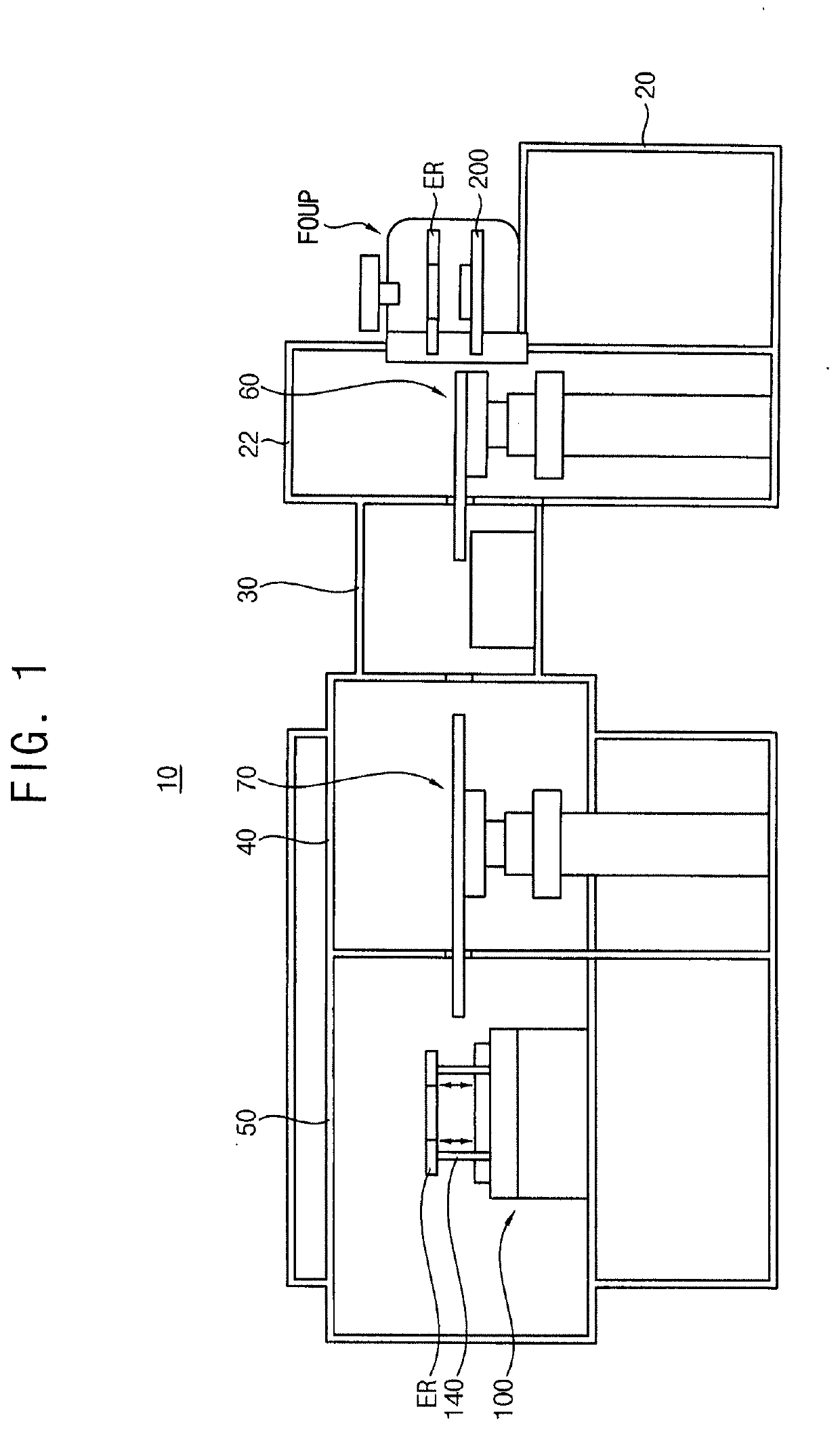
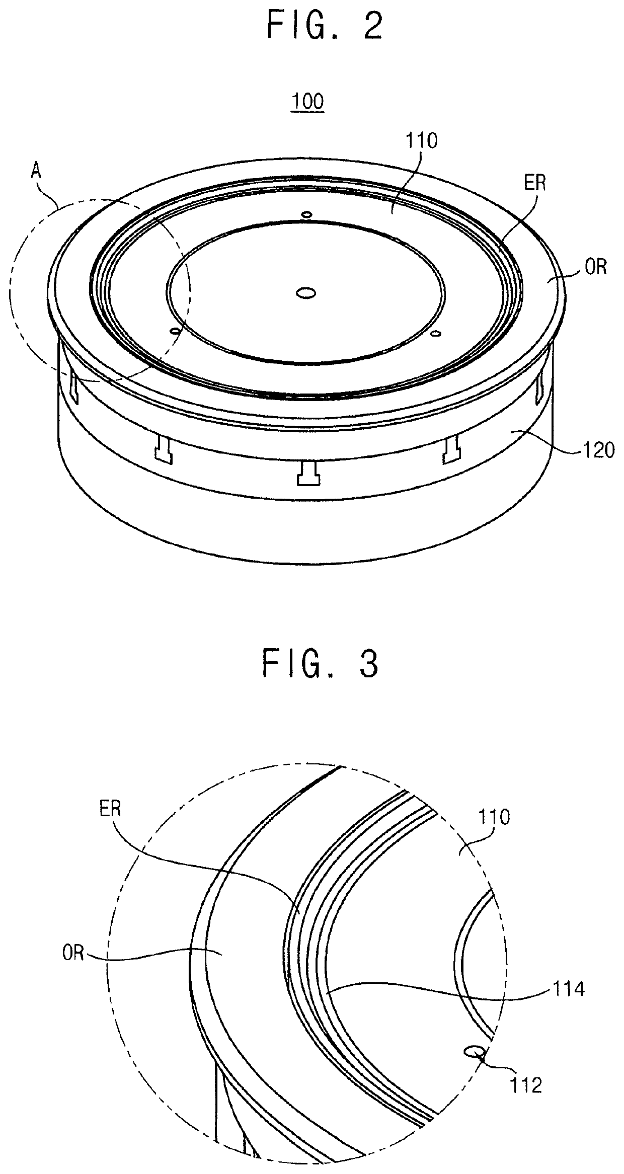
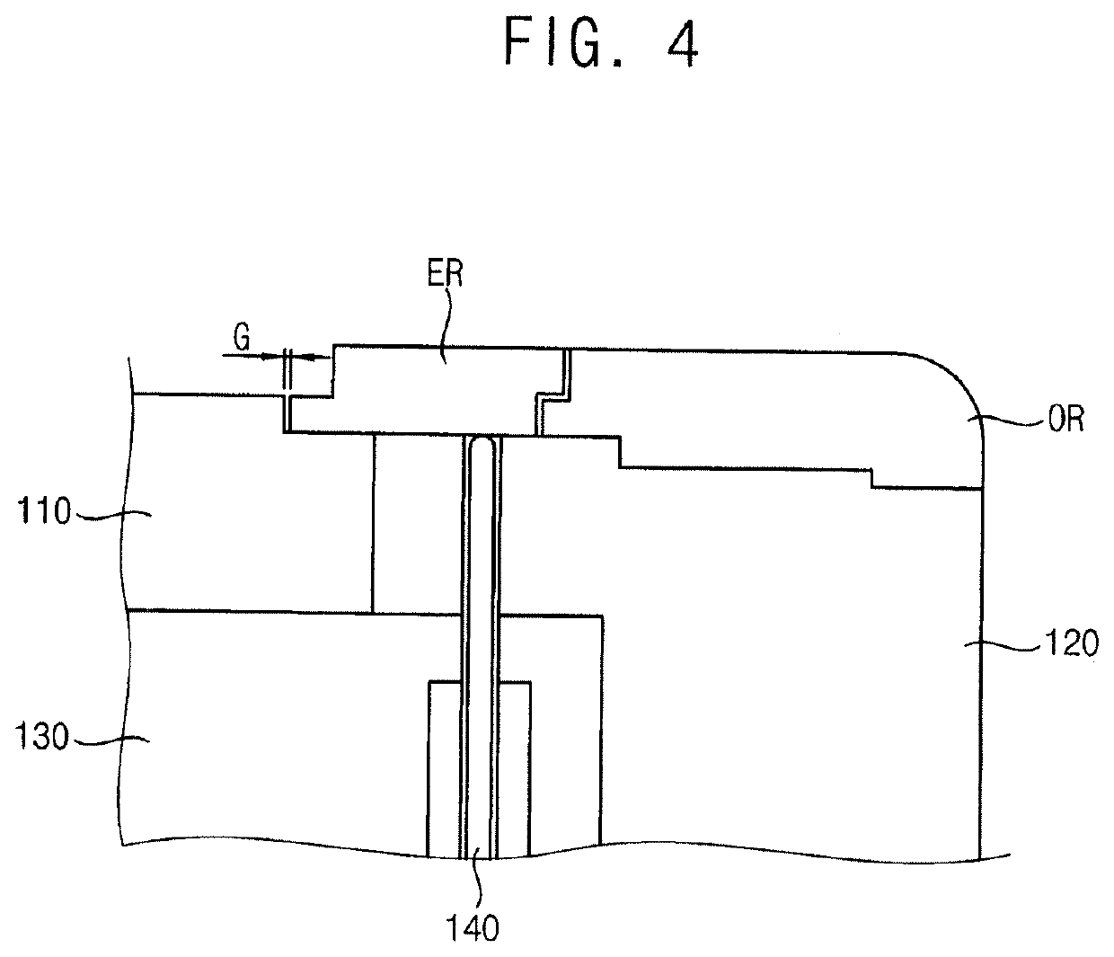
[0028]FIG. 1 is a view illustrating a substrate processing system in accordance with example embodiments. FIG. 2 is a perspective view illustrating a substrate support within a process module in FIG. 1. FIG. 2 is an enlarged view illustrating ‘A’ portion in FIG. 2. FIG. 4 is a cross-sectional view illustrating the substrate support in FIG. 2. FIG. 5 is a block diagram illustrating a controller circuit connected to a lift mechanism and a second transfer robot of the substrate processing system in FIG. 1. FIG. 6A is a plan view illustrating an end effector of the second transfer robot disposed within a vacuum transfer module in FIG. 1. FIG. 6B is a plan view illustrating a wafer transferred by the end effector of FIG. 6A. FIG. 6C is a plan view illustrating an edge ring transferred by the end effector of FIG. 6A. FIG. 6D is a plan view illustrating a disk-type image sensor tr...


PUM


Abstract

A first edge ring is removed from a substrate support within a process module using a transfer robot. The transfer robot is then used to place a second edge ring on the substrate support. An image sensor (e.g., a disk-shaped wireless image sensor) is positioned over the second edge ring using the transfer robot. The image sensor generates image information, which is analyzed to determine alignment of the second edge ring.

Description

PRIORITY STATEMENT[0001]This application claims priority under 35 U.S.C. § 119 to Korean Patent Application No. 10-2018-0077863, filed on Jul. 4, 2018 in the Korean Intellectual Property Office (KIPO), the contents of which are herein incorporated by reference in their entirety.BACKGROUND1. Field[0002]Example embodiments relate to a substrate processing systems and methods. More particularly, example embodiments relate to apparatus and methods for edge ring replacement, inspection and alignment.2. Description of the Related Art[0003]In wafer processing systems, such as semiconductor etching equipment, an edge ring can be a consumable part that is damaged due to ion bombardment from plasma, thus requiring replacement of the damaged edge ring. However, in order to replace the damaged edge ring, the vacuum of a process chamber may need to be broken to allow replacement of the damaged part. Therefore, the process of replacing the damage edge ring may be time consuming and decrease produ...

Claims


Application Information

Patent Timeline
IPC IPC(8): H01L21/68H01J37/32H01L21/67H01L21/687H01L21/683
CPCH01L21/68735H01L21/681H01L21/68707H01J37/32642H01L21/67259H01L21/67242H01L21/6833H01L21/67288H01L21/67253H01J37/3288H01L21/68742H01J2237/334H04N25/70H01L21/68H01L21/68721H01L21/67742H01L21/02
Inventor LEE, JA-WOOKIM, KEON-WOOKIM, SUN-HOKIM, EUNG-SUYOON, BO-RALEE, HYAN-JUNGCHO, TAE-IL
Owner SAMSUNG ELECTRONICS CO LTD
Learn More