Working vehicle with traveling device having wheels

a technology of traveling device and working vehicle, which is applied in the direction of vehicle sub-unit features, couplings, gearing details, etc., can solve the problems of complicated surrounding structure of spline joints, and difficult to discharge abrasion powder generated

Active Publication Date: 2020-01-16
NIHON KENKI CO LTD
View PDF0 Cites 5 Cited by
  • Summary
  • Abstract
  • Description
  • Claims
  • Application Information

AI Technical Summary

Benefits of technology

[0011]The present invention is characterized in that the output shaft is provided with an oil reservoir space which is formed in an axial innermost part of the hole spline to reserve the lubricant oil, an entire circumference oil path which is separated axially toward the base end side from the oil reservoir space and is formed over an entire circumference in an outer circumference side of the output shaft, and an oil path which provides communication between the oil reservoir space and the entire circumference oil path and supplies the lubricant oil supplied to the entire circumference oil path to the oil reservoir space, and an inner diameter dimension of the oil reservoir space is formed to be larger than a tooth root circle diameter of...

Problems solved by technology

However, in a case of using the grease to lubricate the spline joint, it is difficult to discharge abrasion powder generated due to abrasion between the hole spline and the shaft spline to an exterior of the spline joint.
Therefore, there is posed a...

Method used


Image

  • Working vehicle with traveling device having wheels
  • Working vehicle with traveling device having wheels
  • Working vehicle with traveling device having wheels

Examples


first embodiment

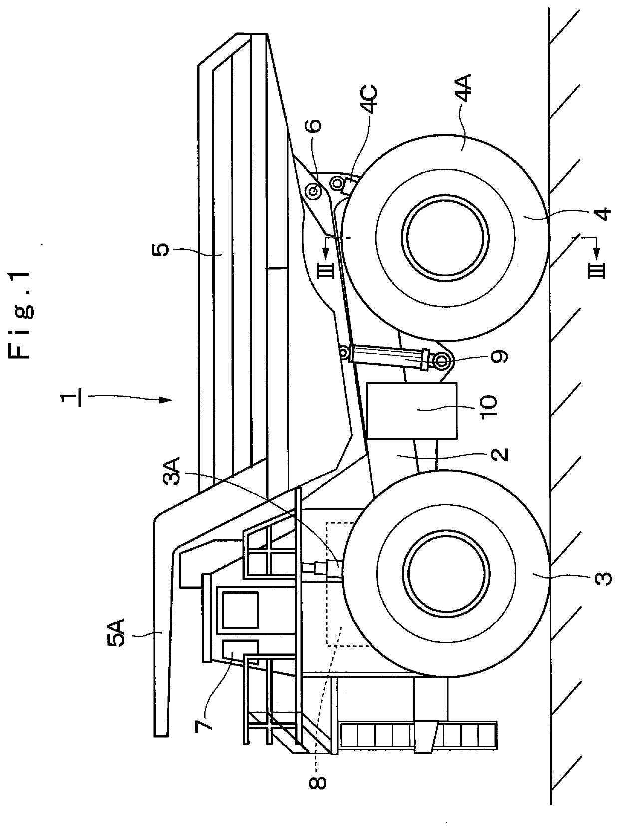
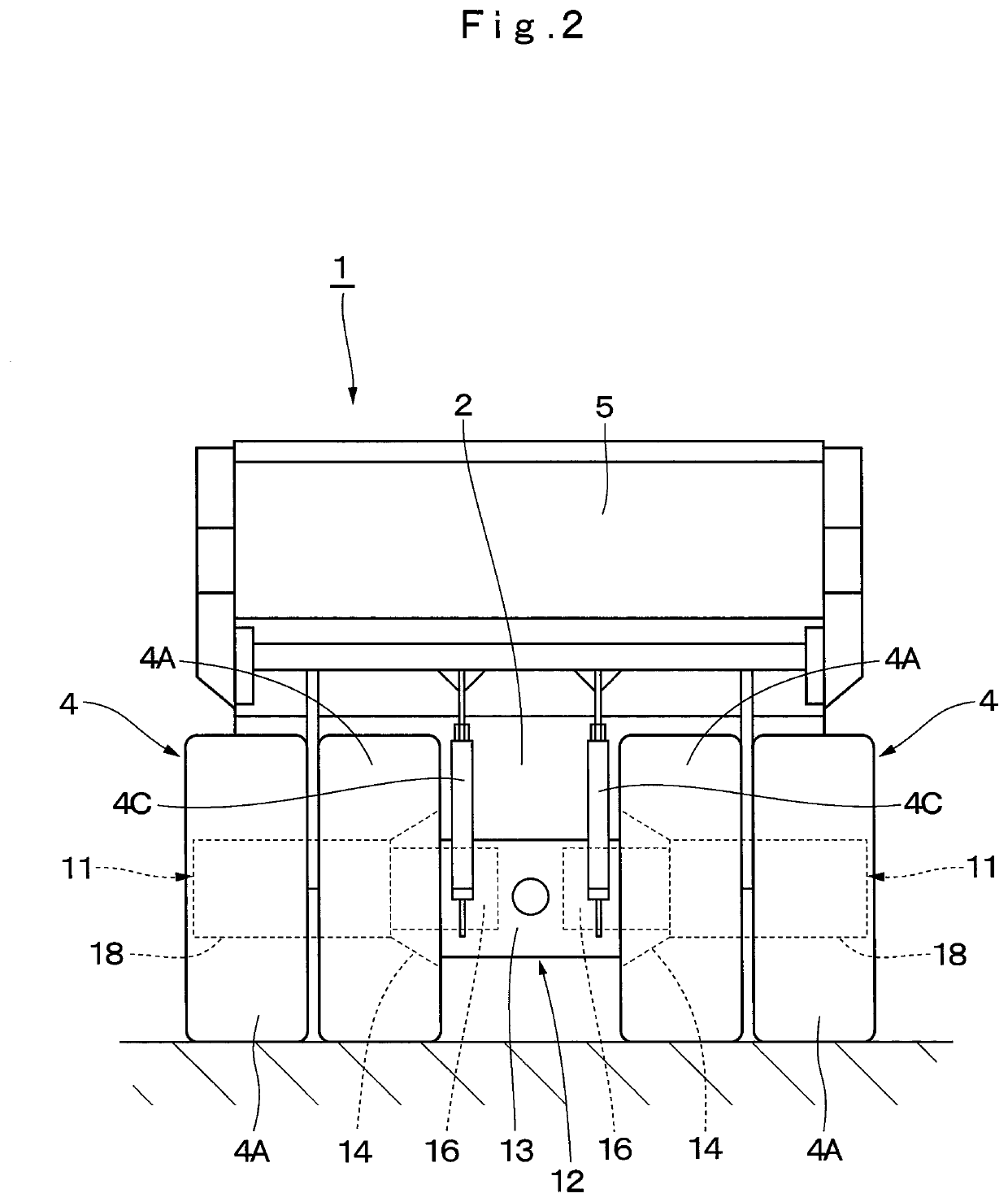
[0026]FIG. 1 to FIG. 11 show the present invention. In FIG. 1 and FIG. 2, a dump truck 1, which is a representative example of a working vehicle with a traveling device having wheels, has a vehicle body 2 of a strong frame structure. Left and right front wheels 3 (only the left side is shown) are rotatably provided in a front part side of the vehicle body 2, and left and right rear wheels 4 are rotatably provided in a rear part side of the vehicle body 2. The left and right front wheels 3 define steering wheels which are steered (a steering operation) by an operator of the dump truck 1. A front wheel side suspension 3A composed of hydraulic shock absorbers and the like is provided between the vehicle body 2 and the left and right front wheels 3.

[0027]The left and right rear wheels 4 define drive wheels of the dump truck 1, and are driven and rotated by an after-mentioned traveling device 11. As shown in FIG. 2 and FIG. 3, the rear wheel 4 is configured to include axial inner and out...

second embodiment

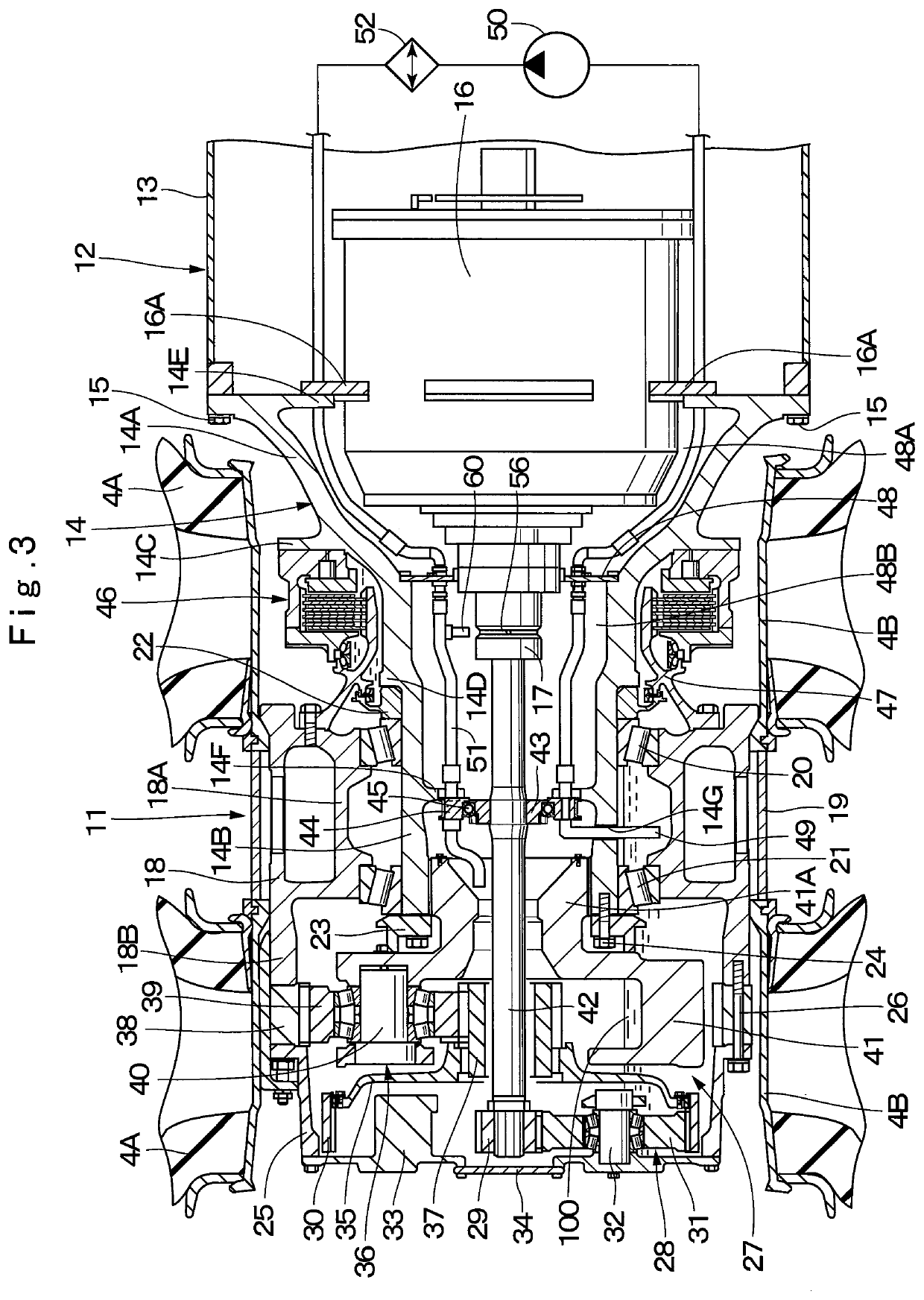
[0098]The traveling device has the lubricating mechanism of the spline joint as described above. At the traveling of the dump truck 1, a part of the lubricant oil 100 delivered to the supply pipe 51 from the lubricant oil pump 50 is supplied to the entire circumference groove 64A of the cylindrical member 64 through the connecting pipe 65 branched from the supply pipe 51. The lubricant oil 100 supplied to the entire circumference groove 64A is introduced via the radial oil path 58 and the axial oil path 59, which are provided in the output shaft 61, to the oil reservoir space 55.

[0099]In addition, at the traveling of the dump truck 1, when the output shaft 61 rotates, the lubricant oil 100 reserved in the oil reservoir space 55 is pushed against the inner peripheral surface 55B of the oil reservoir space 55 by a centrifugal force. Thereby, also in the second embodiment, the lubricant oil 100 flows into the gaps between the respective spline teeth 53B of the hole spline 53 and the r...


PUM


Abstract

A traveling device (11) is provided with an electric motor (16) provided in a vehicle body (2) of a dump truck (1), an output shaft (17) an axial base end of which is connected to the electric motor (16) and which outputs rotation of the electric motor (16), a bottomed hole spline (53) formed in an axial front end of the output shaft (17), and an input shaft (42) which has a shaft spline (54) spline-coupled to the hole spline (53), and inputs the rotation of the output shaft (17) to a reduction gear mechanism (27). The output shaft (17) is provided with an oil reservoir space (55) formed in the innermost part of the hole spline (53), an annular oil groove (56) and an oil path (57) providing communication between the oil reservoir space (55) and the annual oil groove (56). Lubricant oil (100) supplied to the annular oil groove (56) is supplied via the oil path (57) to the oil reservoir space (55), and is supplied to a spline joint between the hole spline (53) and the shaft spline (54) with rotation of the output shaft (17).

Description

TECHNICAL FIELD[0001]The present invention relates to a working vehicle with a traveling device having wheels, such as a dump truck, a wheel type excavator, a wheel loader, and the like.BACKGROUND ART[0002]As a working vehicle having at least four wheels in the left and right sides and the front and rear sides, there is known a large-sized transportation vehicle called a dump truck to be used mainly in an excavating site in a mine. This dump truck is provided with a vehicle body having a frame on which wheels are mounted to be rotatable, and a vessel (a loading platform) provided to be liftable on the frame of the vehicle body. The dump truck travels for transporting cargo such as crushed stones or the like which is excavated in an excavating site by an excavating machine such as a hydraulic excavator and is thereon loaded to a desired transportation place in a state of the cargo being loaded on the vessel (refer to Patent Document 1).[0003]Here, a traveling device of a dump truck i...

Claims


Application Information

Patent Timeline
IPC IPC(8): B60K7/00F16H57/04
CPCF16H57/04B60K2007/0038B60K7/0007F16H57/042F16H57/043B60K17/046F16H57/0482B60Y2200/142B60Y2200/41B60Y2200/412B60Y2200/415B60K2007/0092B60Y2400/73B60Y2306/05B60Y2306/03B60Y2400/4244F16D2300/06F16D3/06F16D1/101F16D2001/103Y02T10/62
Inventor HAGIHARA, SHINICHIROU
Owner NIHON KENKI CO LTD
Why Eureka
Try Eureka