
Cool air supplying apparatus and refrigerator having the same

a cooling apparatus and refrigeration technology, applied in the field of stirring cryocoolers, can solve the problems of difficult optimal design of stirring refrigeration cycles for implementing maximum refrigeration efficiency, long piping, and conventional stirling refrigeration cycles, and achieve the effects of improving heat exchange efficiency, saving energy, and ensuring the same cooling capacity

Active Publication Date: 2020-01-23
SAMSUNG ELECTRONICS CO LTD
View PDF0 Cites 3 Cited by
  • Summary
  • Abstract
  • Description
  • Claims
  • Application Information

AI Technical Summary

Benefits of technology

The patent text discusses a method of cooling refrigerating and freezing compartments using a Stirling cryocooler and a brine circulating system. The technical effect of the patent is to provide an efficient and effective cooling system using a compact and efficient refrigerant. The method reduces the need for long connecting piping and increases the output of the cooling system.

Problems solved by technology

However, such a conventional Stirling refrigeration cycle has the following limitations.
Therefore, it is difficult to optimally design a Stirling refrigeration cycle for implementing the maximum refrigeration efficiency.
However, as a result, the connecting piping becomes longer, and a dead volume, which does not contribute to the compression and expansion of the working fluid, increases, thereby significantly reducing the output.
In addition, there is also a difficulty that the Stirling refrigeration cycle itself becomes large in size by providing the connecting pipe.
Further, when the flow path length of the connecting pipe is long, a flow loss of the working fluid is also generated, and the performance is also deteriorated.
As a result, it is difficult to freely design the number of sets of cylinders while maintaining the phase difference.

Method used


Image

  • Cool air supplying apparatus and refrigerator having the same
  • Cool air supplying apparatus and refrigerator having the same
  • Cool air supplying apparatus and refrigerator having the same

Examples


Embodiment Construction

[0045]FIGS. 1 through 9, discussed below, and the various embodiments used to describe the principles of the present disclosure in this patent document are by way of illustration only and should not be construed in any way to limit the scope of the disclosure. Those skilled in the art will understand that the principles of the present disclosure may be implemented in any suitably arranged system or device.

[0046]Embodiments described in the disclosure and configurations shown in the drawings are merely examples of the embodiments of the disclosure, and may be modified in various different ways at the time of filing of the present application to replace the embodiments and drawings of the disclosure.

[0047]In addition, the same reference numerals or signs shown in the drawings of the disclosure indicate elements or components performing substantially the same function.

[0048]Also, the terms used herein are used to describe the embodiments and are not intended to limit and / or restrict th...


PUM


Abstract

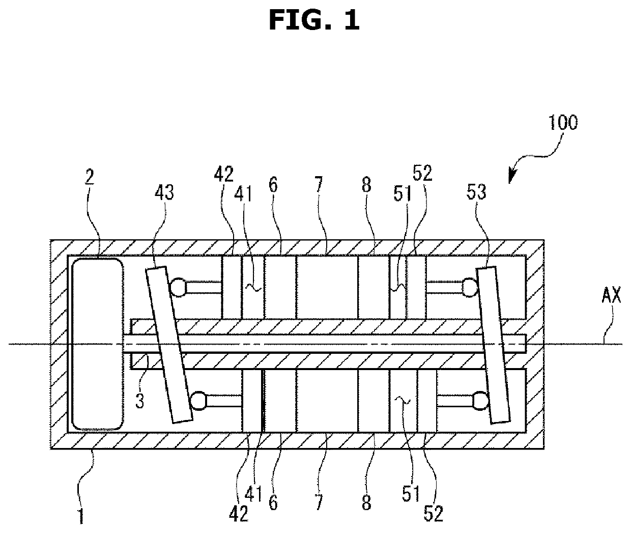
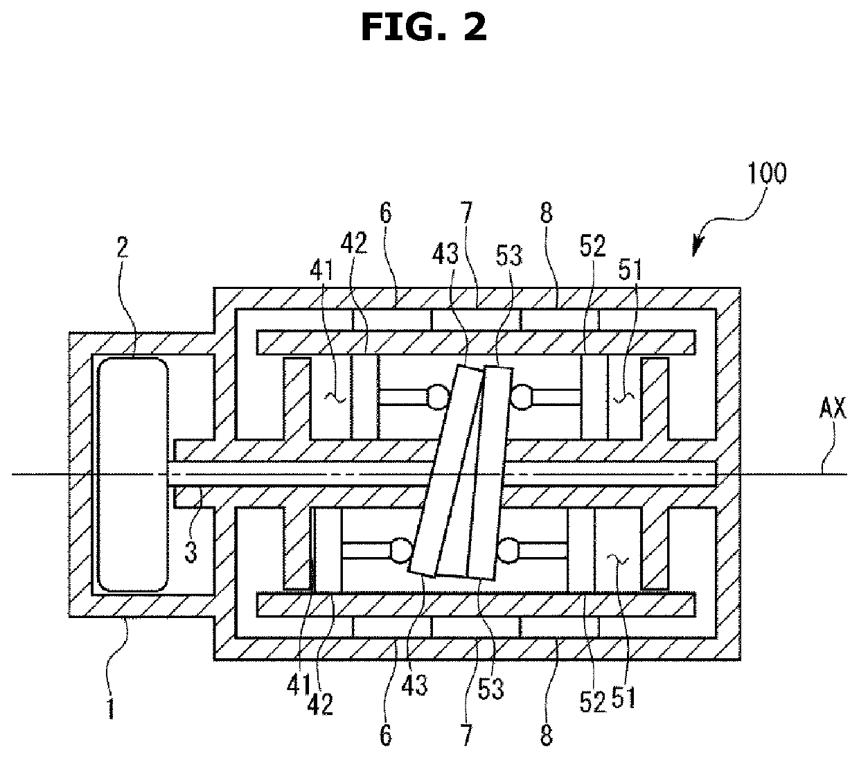
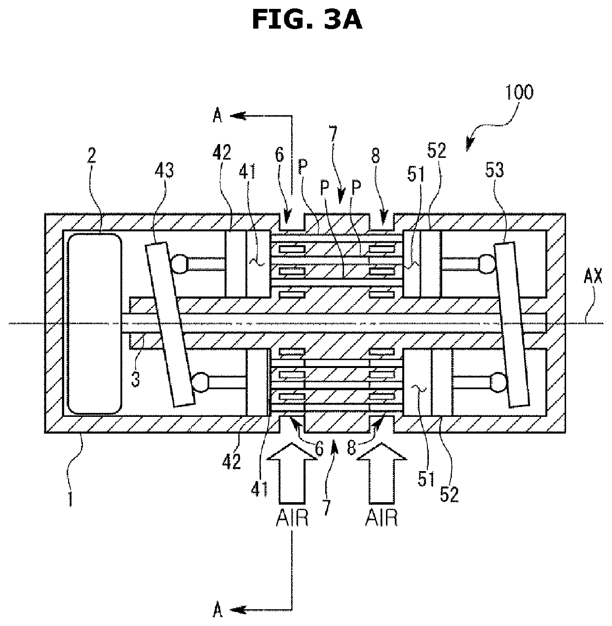
A cool air supplying apparatus includes a swash plate shaft connected to a motor and extending in a predetermined axial direction; a compression swash plate obliquely coupled to the swash plate shaft; a compression piston configured to reciprocate in the axial direction by the rotation of the compression swash plate; a compression cylinder in which a working fluid is compressed by the compression piston, an expansion swash plate obliquely coupled to the swash plate shaft; an expansion piston configured to reciprocate in the axial direction by the rotation of the expansion swash plate; and an expansion cylinder arranged with the compression cylinder in the axial direction and configured to expand a working fluid compressed by the compression cylinder; and the compression swash plate and the expansion swash plate are installed in the swash plate shaft with a predetermined phase difference.

Description

CROSS-REFERENCE TO RELATED APPLICATIONS[0001]This application is based on and claims priority under 35 U.S.C. 119 to Korean Patent Application No. 10-2019-0071642, filed on Jun. 17, 2019, in the Korean Intellectual Properly Office, and Japanese Patent Application No. 2018-137693 filed on Jul. 23, 2018, in the Japan Patent Office, the disclosures of which are herein incorporated by reference in their entiretiesBACKGROUNDField[0002]The disclosure relates to a Stirling cryocooler.Description of Related Art[0003]Energy saving measures for a refrigerator in which the current flows all day is urgent business as a part of solutions for global environmental conservation and global warming. It has been studied to apply a Stirling cryocooler to a refrigerator instead of evaporative refrigeration cycle, as the energy saving measures.[0004]The Stirling cryocooler is operated in such a way that one swash plate is provided about a swash plate shaft rotated by a motor, and an end portion of a comp...

Claims


Application Information

Patent Timeline
Patent Type & Authority Applications(United States)
IPC IPC(8): F25B9/14
CPCF25B9/14F25B2309/1428F25B21/02
Inventor MAKOTO, KOBAYASHITOSHIAKI, SUZUKI
Owner SAMSUNG ELECTRONICS CO LTD
Learn More