
Method for producing an electrode unit for a battery cell and electrode unit

a battery cell and electrode unit technology, applied in the direction of cell components, final product manufacturing, sustainable manufacturing/processing, etc., can solve the problems of delamination, heterogeneity in the curve region, displacement, etc., and achieve the effect of low manufacturing tolerance, high process speed, and improved performance and aging behavior of the electrode uni

Inactive Publication Date: 2020-01-23
ROBERT BOSCH GMBH
View PDF0 Cites 1 Cited by
  • Summary
  • Abstract
  • Description
  • Claims
  • Application Information

AI Technical Summary

Benefits of technology

The invention provides a method for precise positioning of electrode segments relative to separator layers. This allows for high production speeds and low manufacturing tolerances. The method can be used for various types of separator layers, including ceramic coated separators and fiber separators. The active materials of the electrodes are advantageously free from adhesive, and the adhesive used in the adhesive films does not negatively impact the electromechanical behavior of the electrode unit. The adhesive films also protect the electrode unit from foreign particles and prevent shrinkage of the separator layers under excessive thermal load, increasing the reliability of the battery cell.

Problems solved by technology

Depending on the charge state and state of ageing of the electrode unit, an expansion of the electrodes can take place which, in fully wound electrode units, can result in displacements, delaminations and heterogeneities in the region of the curves.

Method used


Image

  • Method for producing an electrode unit for a battery cell and electrode unit
  • Method for producing an electrode unit for a battery cell and electrode unit
  • Method for producing an electrode unit for a battery cell and electrode unit

Examples


Embodiment Construction

[0046]In the following description of the embodiments of the invention, identical or similar elements are denoted by the same reference signs, whereby repeated description of these elements is omitted in individual cases. The figures represent the subject matter of the invention merely schematically.

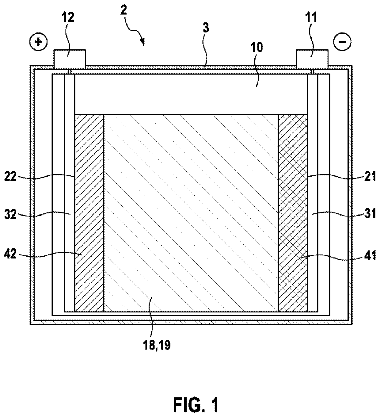
[0047]FIG. 1 shows a schematic illustration of the battery cell 2. The battery cell 2 comprises a housing 3, which is prismatic, in the present case cuboidal, in form. In the present case, the housing 3 is designed to be electrically conductive and is manufactured from aluminum, for example.

[0048]The battery cell 2 comprises a negative terminal 11 and a positive terminal 12. A voltage provided by the battery cell 2 can be picked off via the terminals 11, 12. Furthermore, the battery cell 2 can also be charged via the terminals 11, 12.

[0049]An electrode unit 10, which is constructed as an electrode stack in the present case, is arranged within the housing 3 of the battery cell 2. The elec...


PUM

PropertyMeasurementUnit
widthaaaaaaaaaa
diameteraaaaaaaaaa
diameteraaaaaaaaaa

Abstract

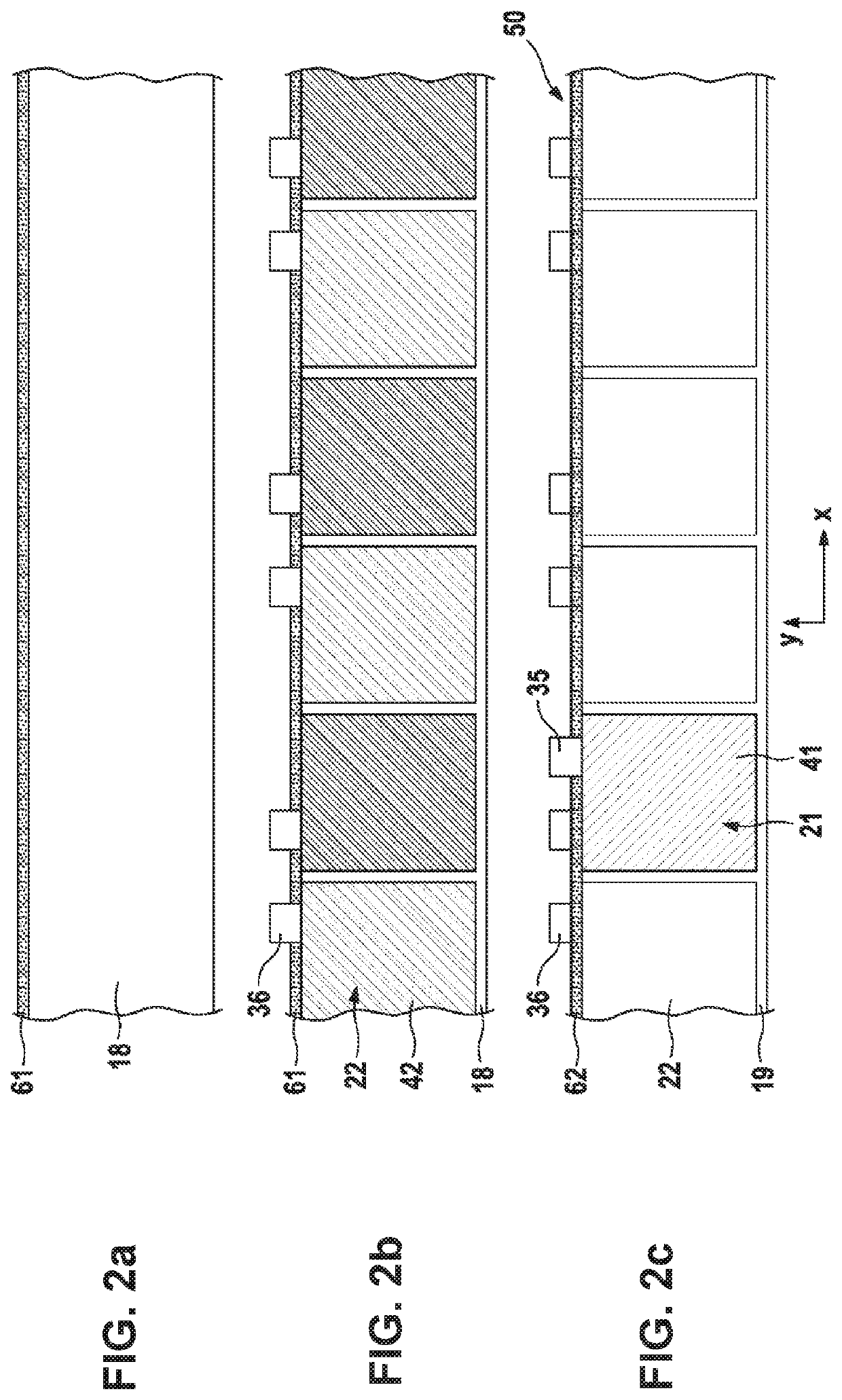
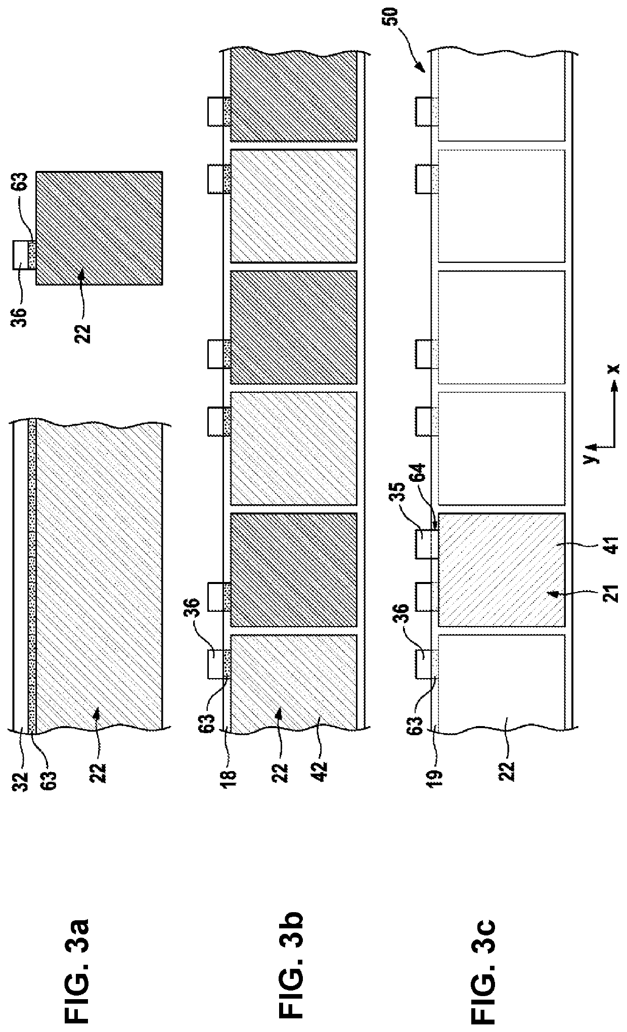
The invention relates to a method for producing an electrode unit for a battery cell comprising the following steps: substance-to-substance bonding of contact lugs (35, 36) of a plurality of plate-shaped segments of a first electrode (21, 22) to a strip-shaped first separator layer (18), substance-to-substance bonding of a strip-shaped second separator layer (19) to the contact lugs (35, 36) of the segments of the first electrode (21, 22) or to the first separator layer (18) such that a strip-shaped composite element (50) is produced, wherein an active material (41, 42) of the segments of the first electrode (21, 22) is surrounded by the first separator layer (18) and by the second separator layer (19), and arranging a plurality of plate-shaped segments of a second electrode (21, 22) on the composite element (50). The invention further relates to an electrode unit for a battery cell, produced by the method according to the invention.

Description

BACKGROUND OF THE INVENTION[0001]The invention relates to a method for producing an electrode unit for a battery cell, wherein a plurality of plate-shaped segments of a first electrode are substance-to-substance bonded, in particular adhesively bonded, to a band-shaped first separator layer. The invention also relates to an electrode unit for a battery cell which is produced in accordance with the method according to the invention.[0002]Electrical energy can be stored by means of batteries. Batteries convert chemical reaction energy into electrical energy. In this case, there is a distinction between primary batteries and secondary batteries. Primary batteries are only functional once, whilst secondary batteries, which are also known as accumulators, are rechargeable. In particular, so-called lithium-ion battery cells are used in an accumulator. These are notable, amongst other things, for high energy densities, thermal stability and an extremely low self-discharge.[0003]Lithium-ion...

Claims


Application Information

Patent Timeline
Patent Type & Authority Applications(United States)
IPC IPC(8): H01M10/04H01M10/0583H01M2/16H01M10/0525
CPCH01M10/0583H01M10/0525H01M10/0459H01M2/168H01M10/058H01M10/0585H01M10/0587Y02E60/10H01M50/461Y02P70/50
Inventor SAUERTEIG, DANIELHEROLD, JUERGENDERRA, MATHIASPOLLER, SILVAN
Owner ROBERT BOSCH GMBH
Learn More