
Open electric pump

a technology of electric pumps and electric valves, applied in the field of open electric pumps, can solve the problems of severe resistance to blood flow, failure of heart failure patients, and insufficient pumping of blood through the patient's circulatory system, and achieve the effects of less shear force, less trauma, and effective pumping of blood

Pending Publication Date: 2020-01-30
SIEGENTHALER MICHAEL
View PDF6 Cites 0 Cited by
  • Summary
  • Abstract
  • Description
  • Claims
  • Application Information

AI Technical Summary

Benefits of technology

The present invention describes a pump with an open design that can be placed in the heart without causing trauma to the blood. The open design also allows for better heat exchange and less blood warming, reducing the likelihood of complications. Additionally, the open pump can be placed endovascularly / minimally invasively.

Problems solved by technology

Heart failure patients have failing hearts that do not adequately pump blood through the patient's circulatory system.
This “closed” design results in severe resistance to blood flow if the motor of the conventional pump stops pumping, which can occur if an associated battery pack becomes drained or if the conventional pump itself malfunctions.
Implanting a conventional pump in series with the blood flow from the heart, such as in the left ventricle outflow tract or within an outflow valve of a main pumping chamber, can lead to catastrophic circulatory collapse if the conventional pump stops pumping, such as during a battery exchange, an inadvertent disconnection of the battery, or pump malfunction.
This can case the blood and surrounding tissue to warm to the point of causing damage to blood proteins and other cellular blood components, possibly leading to clotting and a thromboembolism.

Method used


Image

  • Open electric pump
  • Open electric pump
  • Open electric pump

Examples


Embodiment Construction

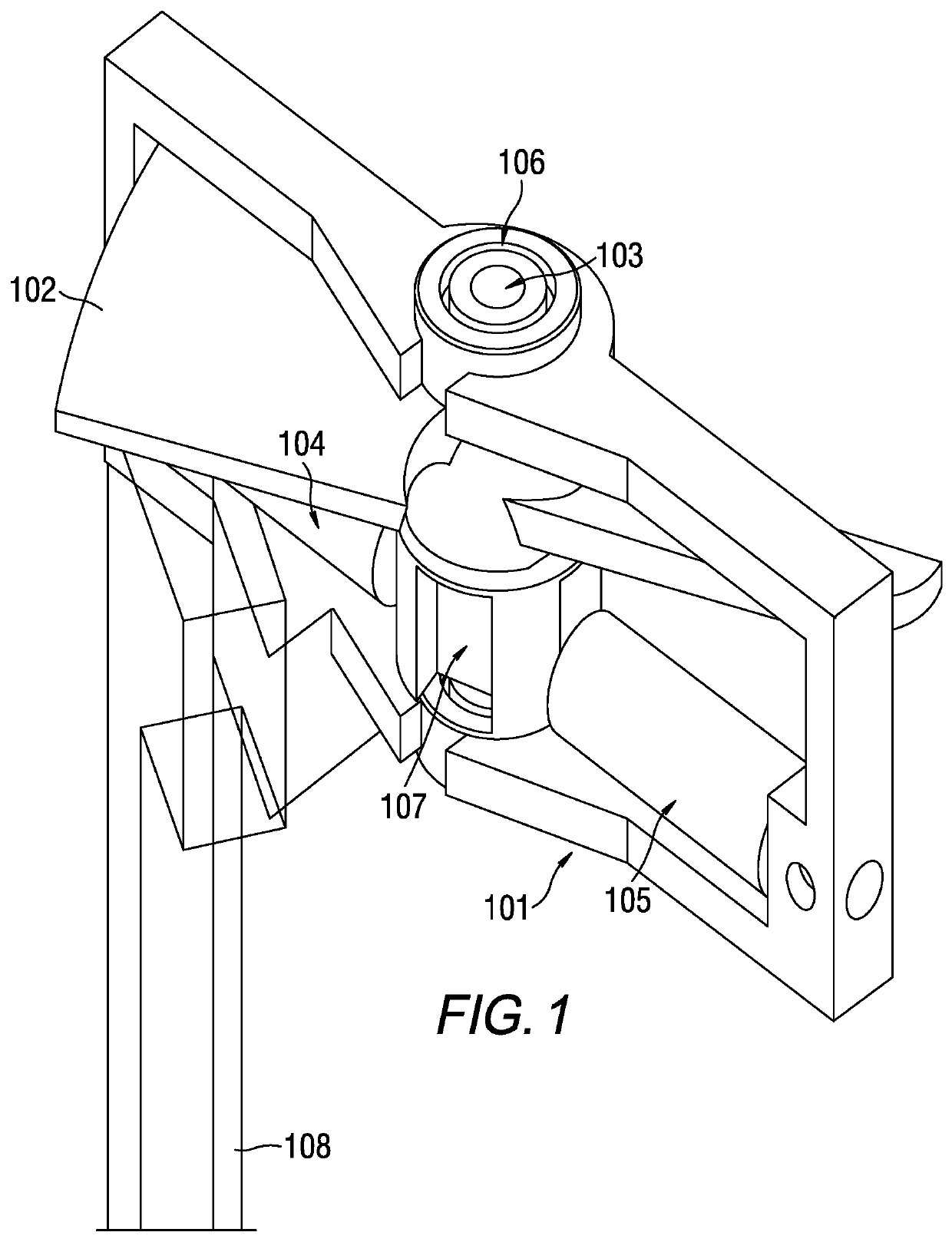
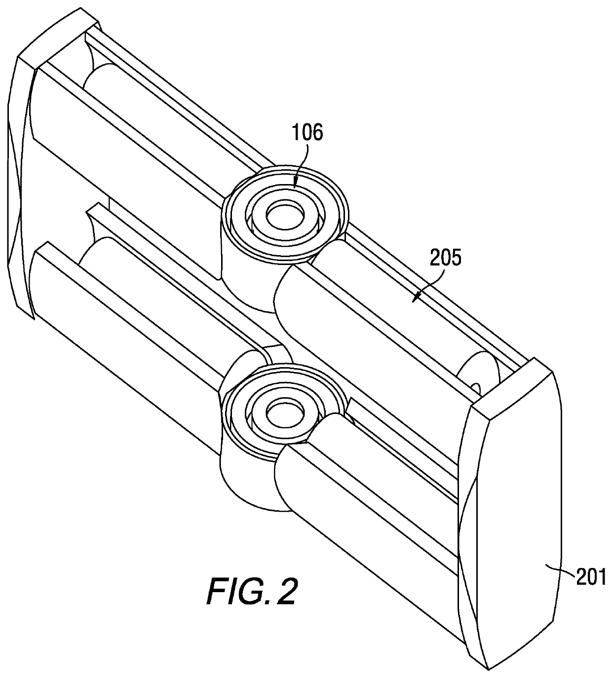
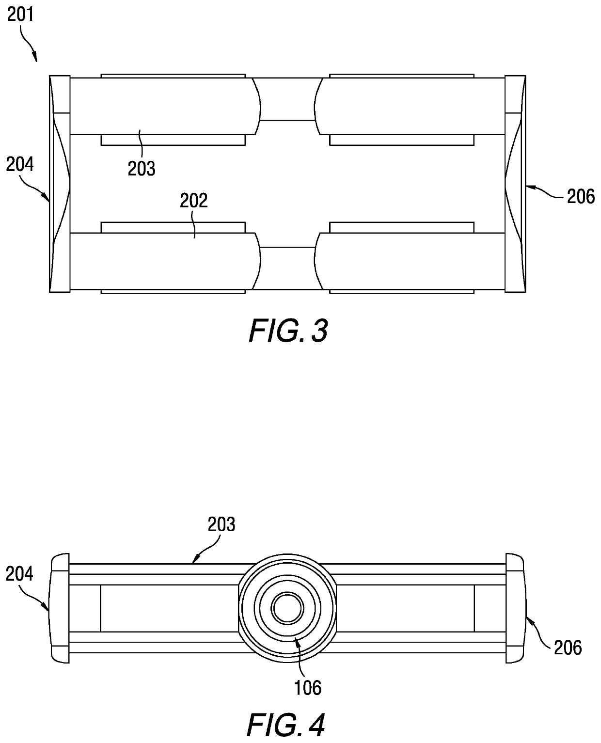
[0021]Referring now to the drawings, wherein like reference numerals designate identical or corresponding parts throughout the several views, FIG. 1 is an open pump according to exemplary aspects of the present disclosure. As illustrated in FIG. 1, the pump includes a frame 101 which holds a central axle 103 onto which a rotor 102 is mounted. Also attached between the central axle 103 and the frame are two electromagnetic coils 104 and 105, which cause the rotor 102 to turn when energized. The coils 104 and 105 are arranged radially or slightly “off-center” within the blood channel. In order to correctly time the signals provided to the electromagnetic coils 104 and 105, a Hall sensor is used or backward electromagnetic pulse sensing (EMP pulse sensing) is used. The pump also includes an opening 107 for insertion of one or more magnets that are used to cause the rotor 102 to rotate, and has a power cable 108 attached to the coils 104, 15 in order to provide power to those coils. The...


PUM


Abstract

An implantable pump is configured to be implanted in series with blood flow from a heart. The pump includes a frame configured to be implanted within the natural blood flow of the heart such as a ventricular outflow tract an outlet valve of the heart, and a central axle configured to be affixed within the frame parallel to the blood flow. The pump also includes a rotor attached to the central axle and configured to rotate in order to pump blood, and at least two electromagnetic coils configured to be energized in order to cause the rotor to rotate.

Description

CROSS-REFERENCE TO RELATED APPLICATIONS[0001]This application claims the benefit of priority of the filing date of provisional application No. 62 / 711,856, the entire contents of which are incorporated herein by reference.BACKGROUNDField[0002]The present disclosure is directed to open electric pumps used to pump fluids. Specifically, the present disclosure describes an open electric pump that may be implanted in a failing heart to assist in the pumping of blood.Description of the Related Art[0003]Heart failure patients have failing hearts that do not adequately pump blood through the patient's circulatory system. Therefore, circulatory assist devices have been developed in order to aid a failing heart to pump blood. Such devices can include rotary axial flow pumps, or centrifugal pumps, that have rotors which pumps blood by spinning. These conventional pumps also include casings that surround the rotor with very small tolerances between the rotor and the casing wall. This “closed” de...

Claims


Application Information

Patent Timeline
IPC IPC(8): A61M1/10A61M1/12
CPCA61M1/1008A61M1/1036A61M2210/12A61M1/125A61M60/422A61M60/216A61M60/81A61M60/139A61M60/13A61M60/538A61M60/419A61M60/135A61M60/205A61M60/857
Inventor SIEGENTHALER, MICHAEL
Owner SIEGENTHALER MICHAEL
Learn More