Air conditioner for vehicle

a technology for air conditioners and vehicles, applied in vehicle components, vehicle heating/cooling devices, transportation and packaging, etc., can solve the problems of fluidity, inability to quickly discharge out air heated in the interior of the vehicle in summer, etc., to reduce the density of carbon dioxide inside the vehicle, enhance fogging speed, and enhance air blast efficiency

Active Publication Date: 2020-01-30
HANON SYST
View PDF0 Cites 4 Cited by
  • Summary
  • Abstract
  • Description
  • Claims
  • Application Information

AI Technical Summary

Benefits of technology

[0034]As described above, due to the indoor air ventilation structure of the air conditioner for a vehicle, the air conditioner for a vehicle according to the present invention can fill the interior of the vehicle with fresh air faster than the conventional air conditioner using the extractor.
[0035]In detail, the air conditioner for a vehicle according to the present invention can discharge the indoor air of the vehicle to the outside and introduce the outdoor air into the interior of the vehicle using the two blowers. Alternatively, one among the two blowers discharges the indoor air of the vehicle to the outside of the vehicle and the other one introduces the outdoor air to the interior of the vehicle. Therefore, the air conditioner for a vehicle according to the present invention can reduce density of carbon dioxide inside the vehicle, remove exhaust gas from the interior of the vehicle, and enhance fog-up speed through forced ventilation.
[0036]Moreover, the air conditioner for a vehicle according to the present invention can make inhalation and flow of the air to the blast fan uniform in order to enhance air blast efficiency since the filter unit is disposed at a front end of the inlet ring of the blower in the air intake direction so that the direction of the air inhaled through the indoor air inlet and the direction of the air introduced into the blast fan are perpendicular to each other.
[0037]Furthermore, the air conditioner for a vehicle according to the present invention can enhance air blowing efficiency through uniform inhalation and flow of air to the blowing fans since the filter units are disposed to be refracted along the air inhalation channel and are formed in a streamlined shape so that air is smoothly introduced into the blowing fans.

Problems solved by technology

However, such an air conditioner is difficult to form a filter in front of the blowers 20 due to a difference in arrangement since the two blowers are arranged to be spaced apart from each other and the indoor air inlet and the outdoor air inlet are located unidirectionally, for instance, in a vertical direction, and is disadvantageous in an aspect of fluidity since straightness of the inhaled air is not guaranteed.
However, because such an extractor 50 is opened just by differential pressure between the interior of the vehicle and the exterior of the vehicle, the air heated in the interior of the vehicle in summer cannot be rapidly discharged out.

Method used


Image

  • Air conditioner for vehicle
  • Air conditioner for vehicle
  • Air conditioner for vehicle

Examples


first embodiment

[0060]FIG. 4 is a perspective view of an air conditioner for a vehicle according to the present invention, and FIG. 5 is a partially perspective view of a blower unit of the air conditioner for a vehicle according to the present invention.

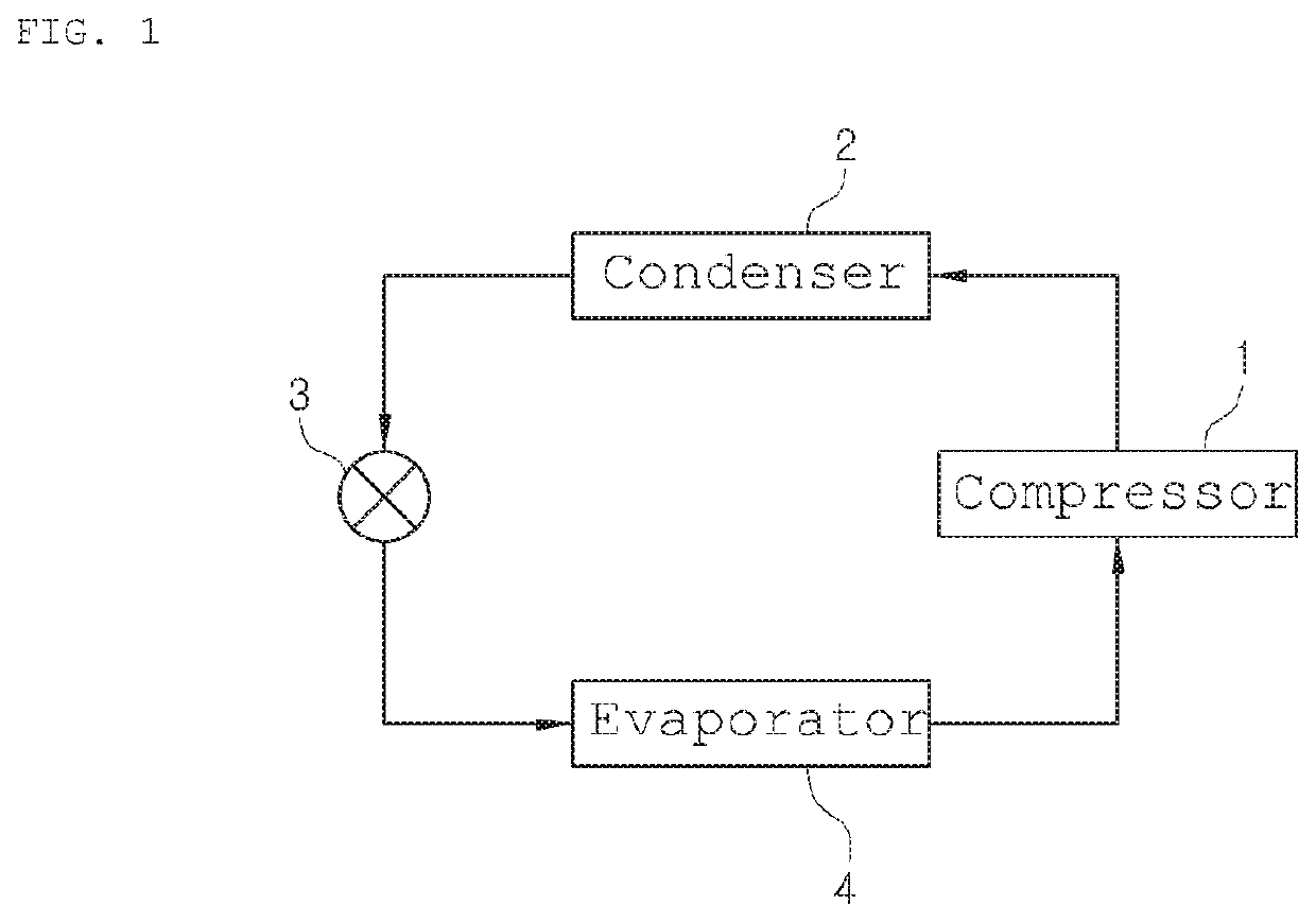
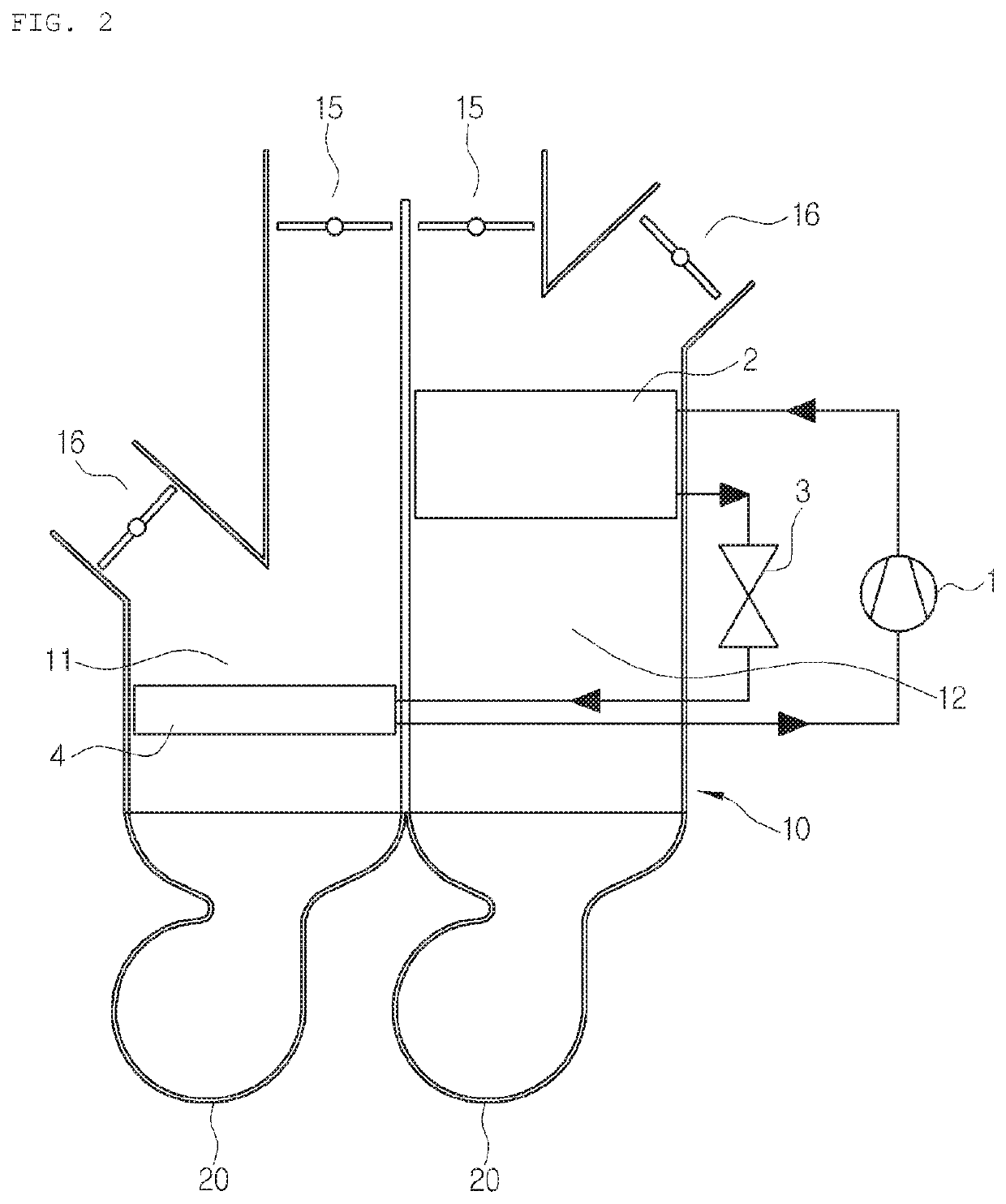
[0061]As shown in FIGS. 4 and 5, the air conditioner for a vehicle according to the present invention includes a compressor (not shown), a condenser 102, expansion means (not shown) and an evaporator 104, which are connected with one another in sequence through a refrigerant circulation line (not shown), so as to carry out cooling through the evaporator 104 and carry out heating through the condenser 102. Description of the refrigerant circulation process will be omitted since the refrigerant circulation process is obvious to those skilled in the art.

[0062]In the above-mentioned refrigerant circulation process, the air blown by a blower unit 130 is introduced into the air-conditioning case 110, is cooled by the evaporative latent heat of the liquid...

second embodiment

[0138]FIG. 17 is a sectional view showing a filter unit according to the present invention.

[0139]As shown in FIG. 17, the filter unit 250 is disposed to be refracted along an air inhalation channel, and may be formed in a streamlined shape for a smooth introduction of the air to the blowing fans 132 and 136. For instance, the filter unit 250 may be formed in a convex shape in the reverse direction of the air inhalation channel of the blowing fans 132a and 136.

[0140]Furthermore, the first filter 251 has a plurality of filter holes 251a, and the filter holes 251a are expanded to get wider toward the blowing fan 132. The air inhalation channel directing from the indoor air inlet 142 to the blowing fan 132 illustrated in FIG. 16 is formed in the top-left direction from the lower portion. In this instance, the air channel in the top-left direction may horizontally enter into the blowing fan 132 after colliding against the gradually expanded filter holes 251a. Therefore, the channel of th...

third embodiment

[0141]FIG. 18 is a sectional view showing a filter unit according to the present invention.

[0142]As shown in FIG. 18, the filter unit 250 has filter holes 251a, which are formed in a hexagonal honeycomb shape. In this instance, the honeycomb-shaped filter unit 250 according to the present invention may be formed integrally with the inlet ring 131a. Moreover, the honeycomb-shaped filter unit 250 has a predetermined thickness so that the channel of the air inhaled to the blowing fan 132 through the filter holes 251a is formed uniformly, thereby enhancing blowing performance.


PUM


Abstract

The present invention relates to an air conditioner for a vehicle, which includes a cold air passageway and a warm air passageway, and two blowers disposed in the air passageways, thereby rapidly ventilating the interior of the vehicle using the two blowers.

Description

TECHNICAL FIELD[0001]The present invention relates to an air conditioner for a vehicle and, more particularly, to an air conditioner for a vehicle which includes a cold air passageway and a warm air passageway, thereby rapidly ventilating the interior of the vehicle using blowers of the air conditioner while performing heating or cooling and enabling blowing fans disposed in the passageways to uniformly inhale and move air.BACKGROUND ART[0002]In general, as shown in FIG. 1, an air conditioner for a vehicle has a refrigeration cycle that includes: a compressor 1 for compressing and discharging refrigerant; a condenser 2 for condensing the refrigerant of high pressure discharged from the compressor 1; an expansion valve 3 for throttling the refrigerant condensed and liquefied in the condenser 2; and an evaporator 4 for exchanging heat between the liquefied refrigerant of low pressure throttled by the expansion valve 3 and air blown to the interior of the vehicle and for evaporating th...

Claims


Application Information

Patent Timeline
Patent Type & Authority Applications(United States)
IPC IPC(8): B60H1/00B60H1/24B60H1/26B60H3/06
CPCB60H1/00828B60H1/26B60H3/06B60H1/00849B60H1/00007B60H1/241B60H1/248B60H1/00821B60H2001/00178B60H1/00057B60H2001/00099B60H2001/00135B60H1/00899B60H1/039B60H1/00864B60H1/008B60H1/00521
Inventor RYU, JAE CHUNKEON, DAE BOKKIM, YUN JINWON, JONG BOLEE, SE MIN
Owner HANON SYST
Why Eureka
Try Eureka