Additional liquid natural gas plant and method of operating thereof

a liquid natural gas and plant technology, applied in the direction of liquidification, lighting and heating equipment, solidification, etc., can solve the problem of energy-consuming process in the liquefaction of natural gas, and achieve the effect of more efficient lng plants

Inactive Publication Date: 2020-01-30
SHELL OIL CO
View PDF2 Cites 1 Cited by
  • Summary
  • Abstract
  • Description
  • Claims
  • Application Information

AI Technical Summary

Benefits of technology

[0007]It is an aim to provid

Problems solved by technology

Liquefaction of natural gas i

Method used


Image

  • Additional liquid natural gas plant and method of operating thereof

Examples


Embodiment Construction

[0050]The following examples of certain aspects of some embodiments are given to facilitate a better understanding of the present invention. In no way should these examples be read to limit, or define, the scope of the invention.

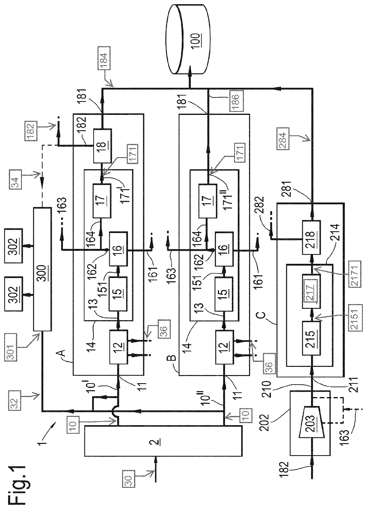
[0051]There is provided a liquid natural gas plant comprising a plurality of liquefaction trains, of which at least one train, referred to as an additional liquefaction train, liquefies gas streams received from the other trains (referred to as treating and liquefaction trains). The additional liquefaction train is preferably added to an existing plant as retrofit.

[0052]In existing plant designs, i.e. plants not comprising an additional liquefaction train as described here, typically fuel is obtained from gas streams obtained from the treatment and liquefaction trains, such as portions of the end flash gas and the overhead of the scrub column used for NGL-extraction, which are relatively lean and clean.

[0053]Now provided is a liquid natural gas plant in whic...


PUM


Abstract

The invention relates to a liquid natural gas plant for producing liquefied natural gas. The liquid natural gas plant comprises two or more parallel treatment and liquefaction trains, each train comprising a cooling stage arranged to receive a cleaned natural gas stream from a gas treatment stage, an NGL-extraction unit for extracting natural gas liquids, thereby generating a light natural gas stream. The liquid natural gas plant comprises an additional liquefaction train, comprising an additional cooling stage arranged to receive an additional feed stream for generating additional liquefied natural gas. The additional feed stream comprises two or more side streams taken from the light natural gas taken from the respective light natural gas streams of the one or more parallel treatment and liquefaction trains.

Description

FIELD OF THE INVENTION[0001]The present invention is directed to liquid natural gas plant comprising a plurality of treatment and liquefaction trains. The invention is further related to a method of retrofitting and / or operating such a liquid natural gas plant.BACKGROUND TO THE INVENTION[0002]Natural gas can be liquefied for purposes of storage and transportation, as it is occupying a smaller volume in liquid state than in gaseous state. Typically, before being liquefied, the natural gas is treated to remove contaminants (such as H2O, CO2, H2S and the like) and heavy hydrocarbon molecules, which may freeze out during the liquefaction process.[0003]Liquefaction of natural gas is an energy consuming process. Designing and operating liquid natural gas plants in the most efficient manner is therefore a constant focus area.[0004]WO2006 / 120127 describes an LNG plant having a single liquefaction train for providing LNG in liquid or “pseudo-liquid” form. The LNG in liquid or “pseudo-liquid”...

Claims


Application Information

Patent Timeline
IPC IPC(8): F25J1/00F25J1/02
CPCF25J2245/02F25J2220/64F25J2220/62F25J2230/30F25J1/023F25J2210/02F25J1/004F25J1/0271F25J1/0025F25J1/0274F25J2245/90F25J1/0022F25J1/0242
Inventor JAGER, MARCO DICKMEIRING, WOUTER JAN
Owner SHELL OIL CO
Why Eureka
Try Eureka