Combined automatic Anti-explosion method for gas drainage pipeline

US20200040726A1Active Publication Date: 2020-02-06CHINA UNIV OF MINING & TECH +1

Image

  • Combined automatic Anti-explosion method for gas drainage pipeline
  • Combined automatic Anti-explosion method for gas drainage pipeline

Examples


Embodiment Construction

[0019]The present invention is further described below.

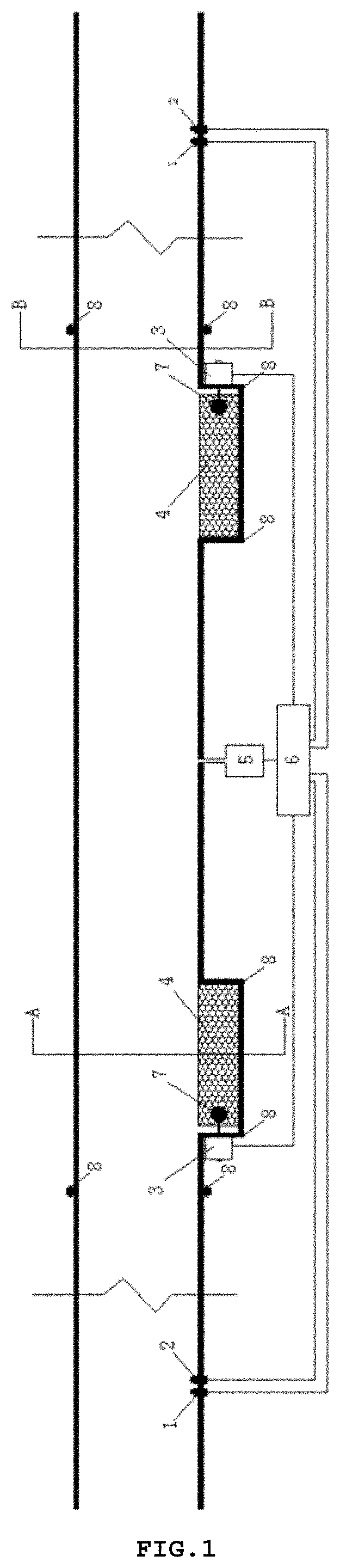
[0020]As shown in FIGS. 1-4, specific steps of the present invention are:

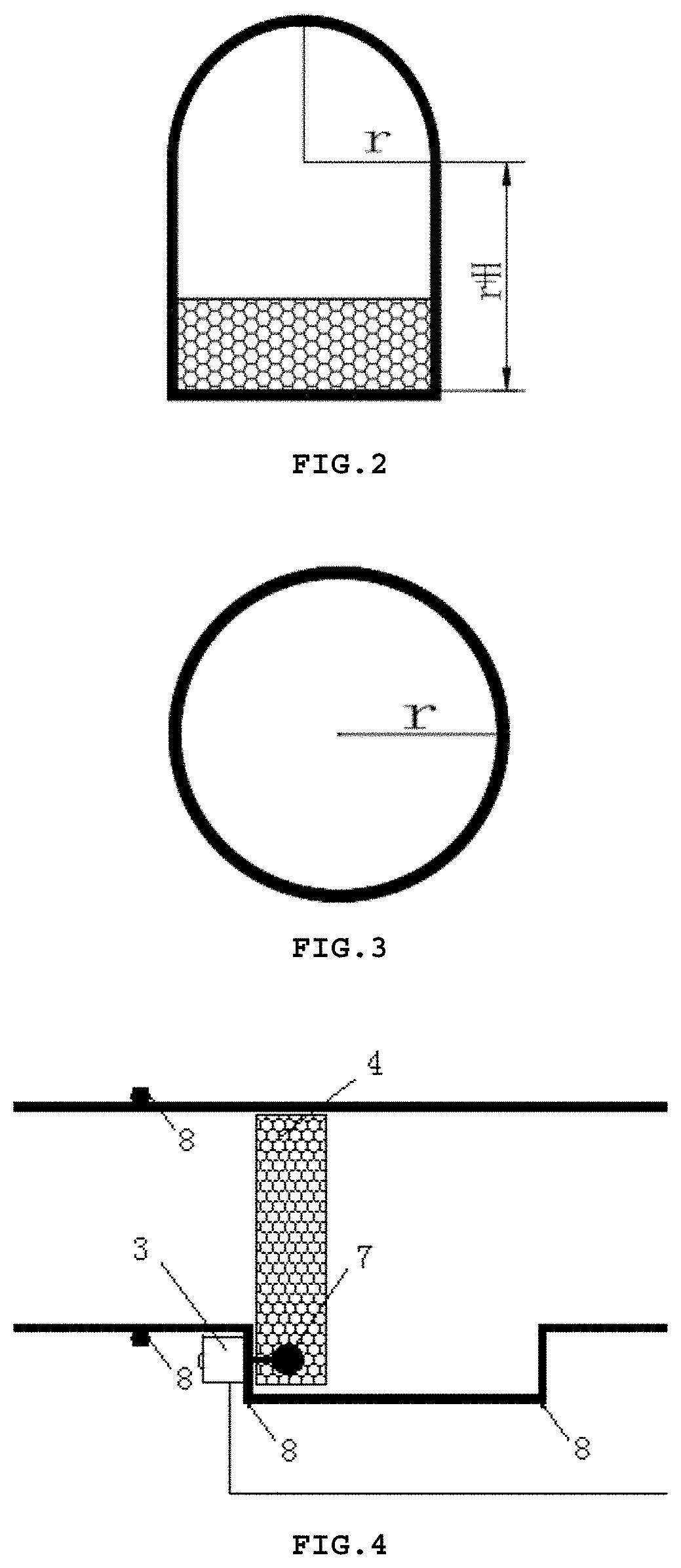
[0021]A. Preparation of an anti-explosion installation piping: a circular pipeline with interfaces at both ends having the same pipe diameter r as a gas drainage pipeline is prepared, and then two arched pipelines are respectively arranged in the piping at 30 cm from the interfaces at both ends, the arc radius of the arched pipeline is the same as the pipe diameter r of the circular pipeline, and the waist height of the arched pipeline is the sum of the pipe diameter r of the circular pipeline and the thickness H of a porous foam material;

[0022]B. Connection of the installation piping and the gas drainage pipeline: in the installation process of the gas drainage pipeline, the anti-explosion installation piping is connected to the gas drainage pipeline and that is sealed by a seal ring coated with petrolatum to prevent air leakage;

[0023]C. Assembly of a poro...


PUM


Abstract

The present invention discloses a combined automatic anti-explosion method for a gas drainage pipeline, comprising specific steps of: preparation of an anti-explosion installation piping; connection of the installation piping and the gas drainage pipeline; assembly of a porous foam material and an automatic control valve; installation of an automatic powder-spraying device and a signal analyzer; installation of a temperature sensor and a pressure sensor; and signal processing and automatic anti-explosion. According to the present invention, the porous foam material is located in a bottom groove of an arched pipeline when no gas explosion occurs in the gas drainage pipeline, without affecting the extraction effect of the gas drainage pipeline. If a gas explosion occurs, the present invention blocks the pipeline with the porous foam material due to its fire resistance and pressure reduction performances, and the automatic powder-spraying device sprays a certain amount of a dry powder explosion suppressant to reduce the explosion overpressure generated in the gas explosion process and isolate the propagation of flame, so that the safety performance of the gas drainage pipeline is ensured, and thus the safety production of coal mines can be ensured.

Description

BACKGROUND OF THE INVENTION1. Field of the Invention[0001]The present invention relates to an automatic anti-explosion method, and in particular, to a combined automatic anti-explosion method for a gas drainage pipeline.2. Description of the Prior Art[0002]In recent years, with the massive consumption of coal energy, coal mining has gradually developed into deep mining, and that is accompanied by a gradual increase in surrounding rock stress, so that a large amount of gas is accumulated. High concentrations of gas have a very negative impact on underground coal production. Gas extraction is a basic method for coal gas control, and it is also a basic means of gas utilization. Gas extraction technology is attracting more and more attention from all over the world. At present, the piping for gas extraction and utilization systems used in China can be summarized as two types, i.e., automatic fire extinguishing and anti-explosion devices and mechanical anti-explosion devices. The automat...

Claims


Application Information

Patent Timeline
06 Feb 2020
Publication
US20200040726A1
IPC
E21F7/00
CPC
E21F5/04; E21F17/107; E21F7/00; E21F17/103; E21F5/143; E21F5/08; E21F5/00
Inventors
LU, CAIPING; ZHANG, HENG