
Cannula, ecmo assistance system

a technology of ecmo and cannula, applied in the field of cannula, can solve problems such as thrombosis or occlusion, and achieve the effect of reducing turbulen

Active Publication Date: 2020-02-20
ASSISTANCE PUBLIQUE HOPITAUX DE PARIS
View PDF0 Cites 2 Cited by
  • Summary
  • Abstract
  • Description
  • Claims
  • Application Information

AI Technical Summary

Benefits of technology

The patent text describes a device used to reduce the risk of arterial occlusion and ischaemia during surgery. This device includes a cannula with a main lumen and a second distal end with a lateral aperture. This design helps to minimize the chances of blood flow obstruction when removing the device from the patient. The technical effect of this invention is to provide a safer and more effective solution for reducing the risk of limb ischaemia during surgery.

Problems solved by technology

Indeed, by inserting a secondary lumen into an artery the passing section of the blood is reduced, and this can cause a thrombus or an occlusion.

Method used


Image

  • Cannula, ecmo assistance system
  • Cannula, ecmo assistance system
  • Cannula, ecmo assistance system

Examples


second embodiment

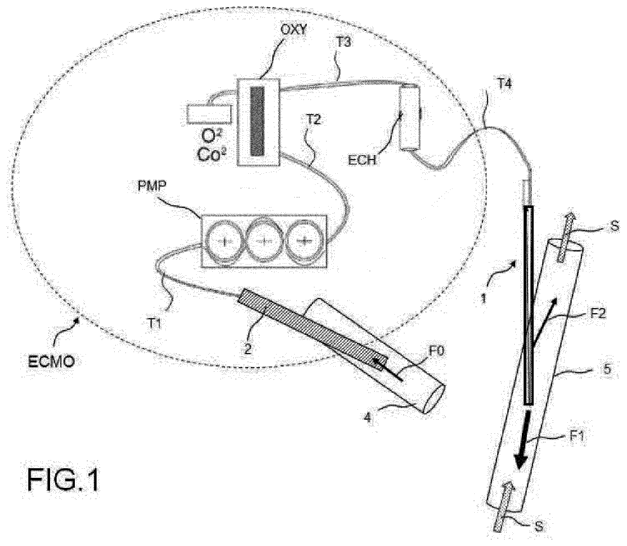
[0089]According to one embodiment, the ECMO system includes a tank (not represented). The function of this tank is to regulate the flow rate of treated blood. Inflow cannula 2 takes a volume FO of blood which is conveyed to the tank. this step is accomplished before the pumping step.

[0090]According to one example implementation, pump PMP is of the “centrifugal” type. A centrifugal pump PMP uses the rotational motion of a wheel inserted in pump PMP. The movement and the flow rate of the fluid can thus be set and controlled. According to another embodiment the pump PMP has “wheels” and is also called “peristaltic”. According to one embodiment, pump PMP generates a drawn flow rate.

[0091]Oxygenator OXY includes a membrane which artificially reproduces the function of the alveolar-capillary membrane. This membrane enables gaseous exchanges to be made in order to oxygenate the blood and to eliminate the carbon dioxide contained in the blood by decarboxylation. Oxygenator OXY is connected...

first embodiment

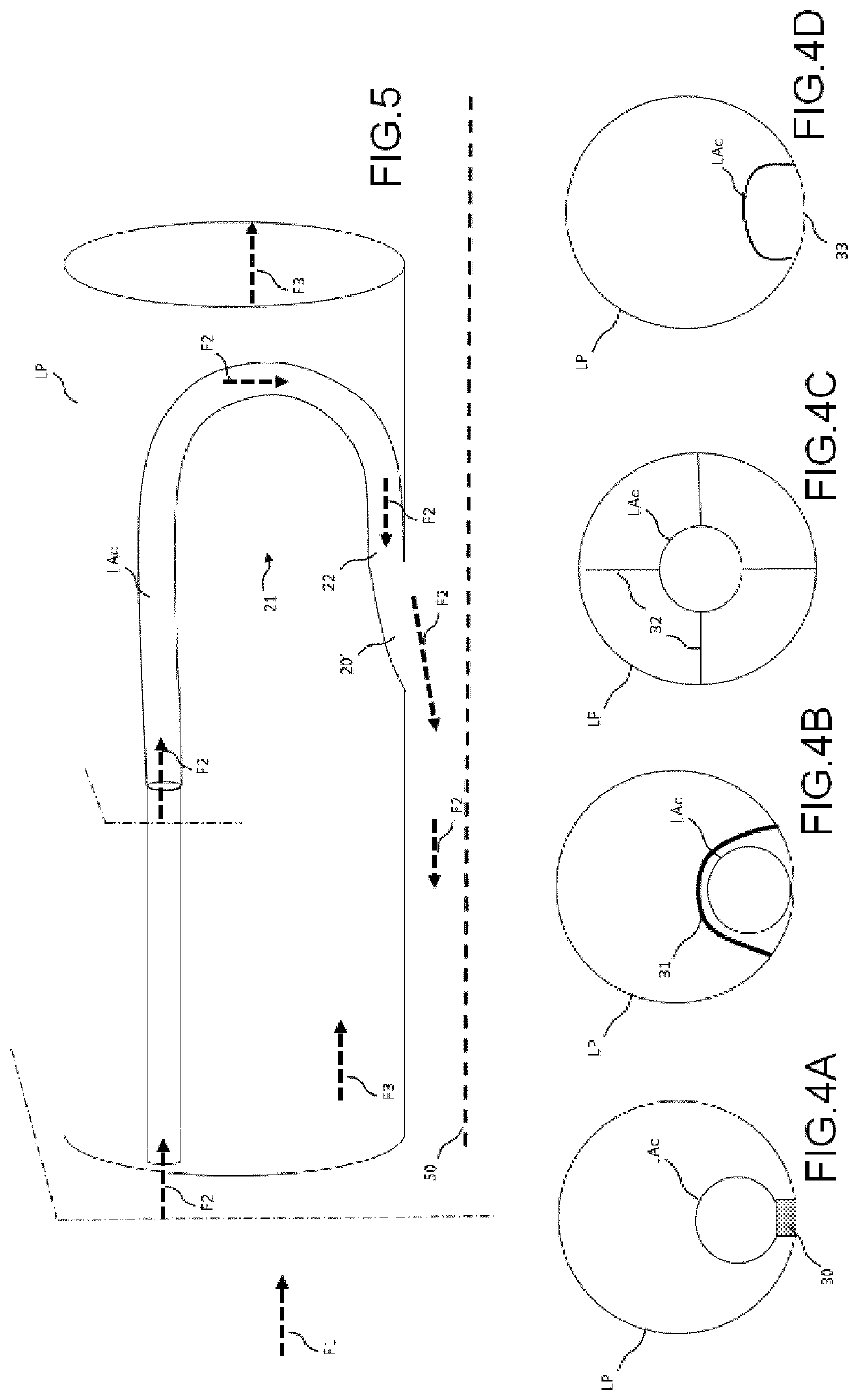
[0107] secondary lumen LAc is a structural lumen associated from main lumen LP. FIGS. 4A to 4C represent various implementation variants, in each of which a cross-section of each of lumens LAc and LP is represented. In this case, secondary lumen LAc can be attached to main lumen LP by a flexible or rigid attachment 30, 31, 32. According to one embodiment, cannula 1 includes means 30, 31, 32 to hold secondary lumen LAc. For example, the holding means can be attachment rings 31 distributed along a portion of main lumen LP. According to another example implementation, the holding means can be formed from a rail 30 extending along a portion of the two lumens, where secondary lumen LAc and main lumen LP then include, respectively, a longitudinal male connector and respectively a longitudinal female connector or, conversely, cooperating together, so as to connect the two lumens LAc and LP together securely.

[0108]According to another implementation variant, secondary lumen LAc is held roug...


PUM

PropertyMeasurementUnit
Lengthaaaaaaaaaa
Lengthaaaaaaaaaa
Luminous fluxaaaaaaaaaa

Abstract

A cannula for the circulation of a fluid in an artery, includes a main lumen conveying a volume of fluid towards a first distal end; an accessory lumen including at least one inner portion arranged inside the main lumen, including: a proximal end situated downstream from the proximal end of the main lumen so as to capture a fraction of the flow of fluid entering the main lumen; a bent portion modifying the direction of flow of the fluid flow captured by the accessory lumen with respect to the direction of flow of the fluid emerging from the first end; a second distal end situated upstream from the first distal end of the main lumen, emerging on a side opening of the cannula so as to direct the captured fraction of liquid in the modified direction of flow.

Description

TECHNICAL FIELD OF THE INVENTION[0001]The present invention concerns a cannula for injection of a fluid in an organ, an arterial or venous blood vessel, a lymphatic vessel or a bronchial structure. More specifically, the field of the invention relates to cannulas for extracorporeal systems allowing oxygenation of a blood flow which is sampled and reintroduced into an organ or vessel identical to or different from the organ or vessel where the sample was taken. More specifically, the field of the invention relates to cannulas for dECMO (Extra Corporeal Membrane Oxygenation) systems allowing oxygenation of a blood flow which is taken and reintroduced into an organ or vessel. Finally, the invention relates in particular to ECMO-VA (veno-arterial) devices allowing a first volume of oxygenated blood to be conveyed in an artery in the retrograde direction, and a second volume of oxygenated blood to be conveyed in the said artery in the anterograde direction.TECHNOLOGICAL BACKGROUND OF THE...

Claims


Application Information

Patent Timeline
IPC IPC(8): A61M1/36A61M1/16A61M1/26A61L29/08A61M39/24
CPCA61M2039/2406A61M1/1698A61M39/24A61M1/267A61M2205/3334A61M2205/0238A61M1/3659A61M2206/11A61L29/085A61L2300/42A61M2205/3337A61L2300/236A61M1/1603A61M2039/2426A61M1/1629A61M25/0029A61M25/007A61M2025/0039A61M2025/0073A61M1/3623
Inventor MORDANT, PIERRE
Owner ASSISTANCE PUBLIQUE HOPITAUX DE PARIS
Learn More