Process improvement through the addition of power recovery turbine equipment in existing processes

a technology of power recovery turbine and process, which is applied in the direction of steam engine plants, machines/engines, mechanical equipment, etc., can solve the problems of energy inefficiency, poor payback of energy conservation projects, and oversize of compressors and pumps

Active Publication Date: 2020-02-20
UOP LLC
View PDF0 Cites 4 Cited by
  • Summary
  • Abstract
  • Description
  • Claims
  • Application Information

AI Technical Summary

Problems solved by technology

However, due to the need to conserve capital by minimizing the number of pieces of equipment, compressors and pumps are often over-sized as the process stream is compressed or pressurized with a compressor or pump up to a single high pressure header and then manifolded downstream to several downstream branches having signif...

Method used


Image

  • Process improvement through the addition of power recovery turbine equipment in existing processes
  • Process improvement through the addition of power recovery turbine equipment in existing processes
  • Process improvement through the addition of power recovery turbine equipment in existing processes

Examples


specific embodiments

[0073]While the following is described in conjunction with specific embodiments, it will be understood that this description is intended to illustrate and not limit the scope of the preceding description and the appended claims.

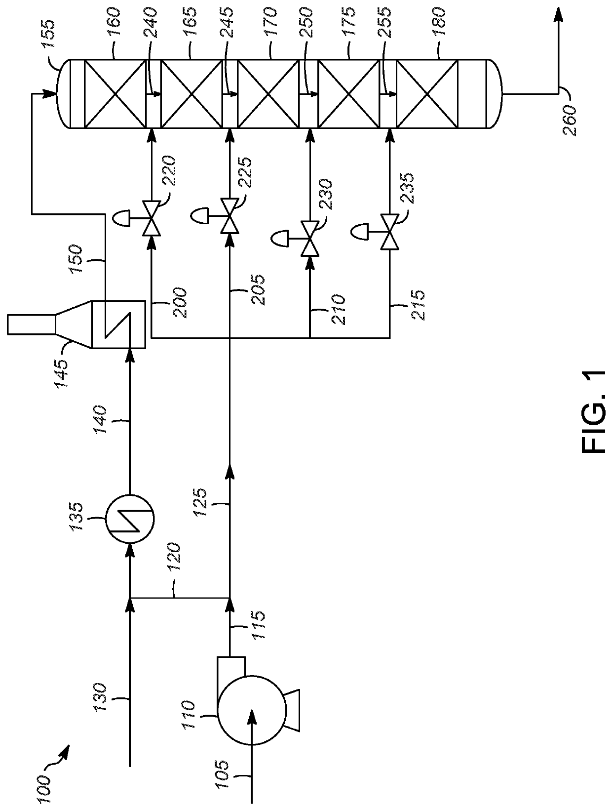
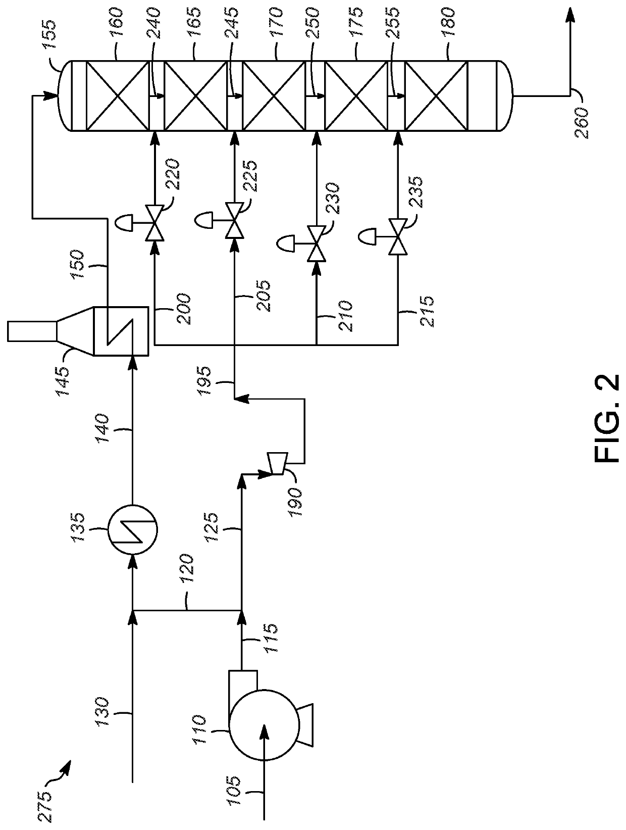
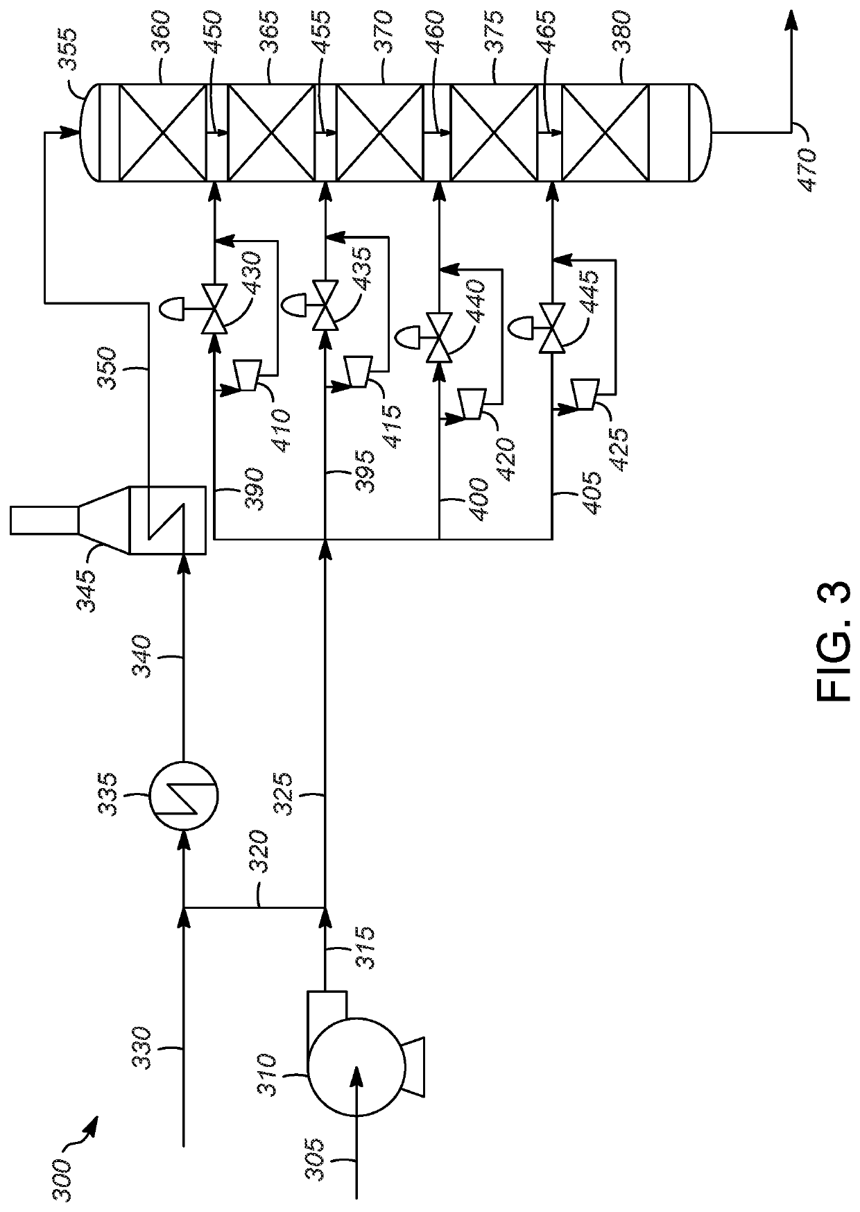
[0074]A first embodiment of the invention is a process for recovering energy in a petroleum, petrochemical, or chemical plant comprising identifying a first fluid stream having a first control valve thereon in a process zone; installing a first power-recovery turbine at the location of the first control valve; directing at least a portion of the first fluid stream through the first power-recovery turbine to generate electric power therefrom; and recovering the electric power. An embodiment of the invention is one, any or all of prior embodiments in this paragraph up through the first embodiment in this paragraph wherein the first power-recovery turbine is installed in parallel with the first control valve. An embodiment of the invention is one, any or all of ...


PUM


Abstract

Power recovery turbines can be used debottlenecking of an existing plant, as well as recover electric power when revamping a plant. A process for recovering energy in a petroleum, petrochemical, or chemical plant is described. A fluid stream having a first control valve thereon is identified. A first power-recovery turbine is installed at the location of the first control valve, and at least a portion of the first fluid stream is directed through the first power-recovery turbine to generate electric power as direct current therefrom. The electric power is then recovered.

Description

CROSS-REFERENCE TO RELATED APPLICATIONS[0001]This application is a Continuation of copending application Ser. No. 15 / 923,964 filed Mar. 16, 2018, which is incorporated herein by reference in its entirety.BACKGROUND OF THE INVENTION[0002]Minimization of power consumption in mechanical drives (pumps and compressors) can be done by a detailed evaluation of the required power and heat inputs during the new unit design step, looking for areas where the energy addition can be minimized. However, due to the need to conserve capital by minimizing the number of pieces of equipment, compressors and pumps are often over-sized as the process stream is compressed or pressurized with a compressor or pump up to a single high pressure header and then manifolded downstream to several downstream branches having significant pressure reduction to much lower pressure services manifesting the inherent energy inefficiency resulting from the minimal capital design. Even in situations where there is no mani...

Claims


Application Information

Patent Timeline
IPC IPC(8): F01K7/16C10G65/02H02J3/46F01K23/06
CPCF05D2220/62C10G65/02H02J3/46F01K23/064F01K7/165F05D2220/31F05D2220/762C10G49/26
Inventor FREY, STANLEY J.EBNER, THOMAS
Owner UOP LLC
Why Eureka
Try Eureka