
Air conditioning unit for vehicle

Active Publication Date: 2020-02-27
DENSO CORP
View PDF3 Cites 1 Cited by
  • Summary
  • Abstract
  • Description
  • Claims
  • Application Information

AI Technical Summary

Benefits of technology

The patent provides an air conditioning system for vehicles that reduces temperature differences and pressure drop. The system uses a tunnel with two angles that allows for better mixing of cool and warm air. By preventing air from flowing through the grid inside the case, the system prevents an increase in pressure loss. The air flows smoothly through the tunnel and mixes with the air outside the tunnel, reducing temperature variations. This results in a more consistent air temperature discharge from the system.

Problems solved by technology

However, when the two angles are equal to or similar to each other, the cool air and the warm air flowing out of the warm air tunnel may not be mixed with each other sufficiently.
As a result, it may be difficult to reduce the temperature variation in the air discharged from the air conditioning unit.
However, when the warm air tunnel is divided into a plurality of paths, a pressure loss in the air conditioning unit may increase due to an increase of a ventilation resistance caused by the grid.
At the same time, the grid may cause noise.

Method used


Image

  • Air conditioning unit for vehicle
  • Air conditioning unit for vehicle
  • Air conditioning unit for vehicle

Examples


first embodiment

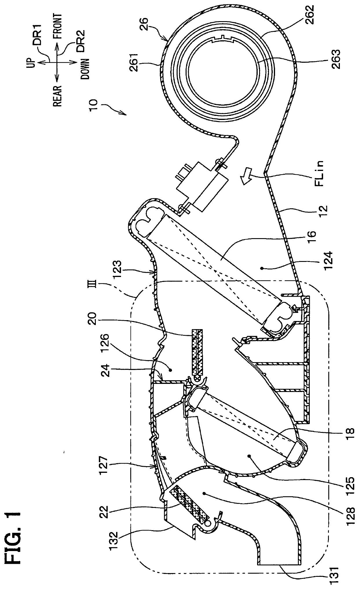
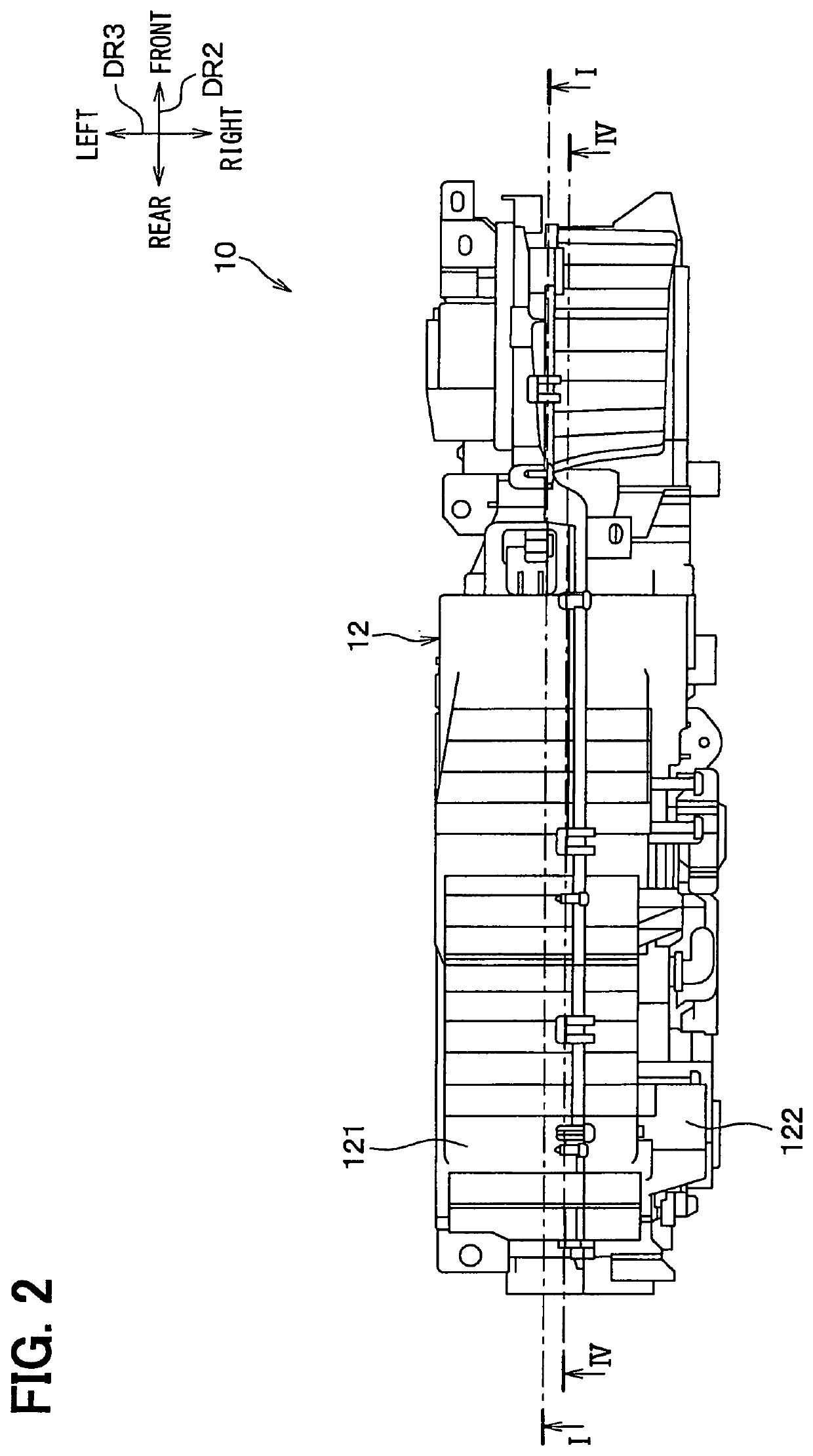
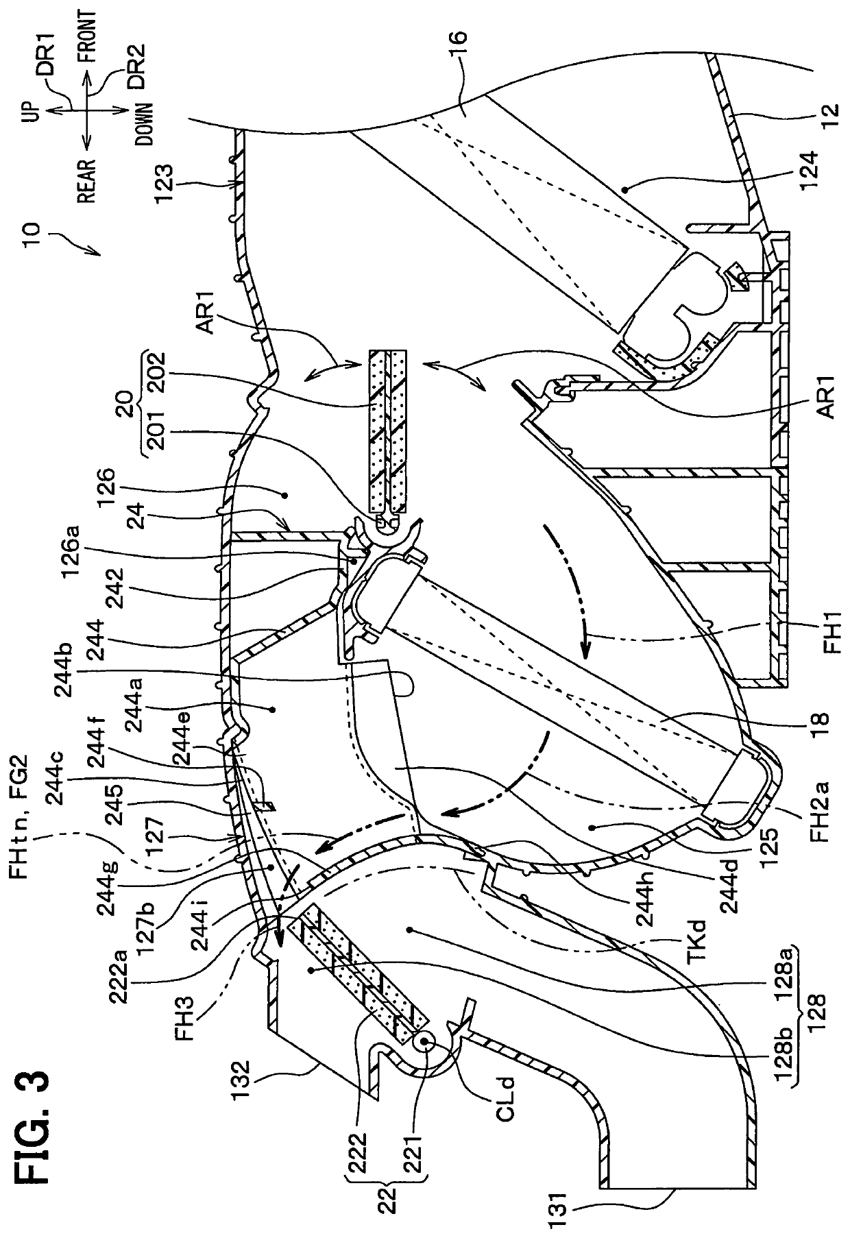
[0030]FIG. 1 is a cross-sectional view illustrating a schematic configuration of an air conditioning unit 10 for a vehicle according to the present embodiment. Specifically, FIG. 1 is taken along a line I-I shown in FIG. 2, which is a plan view of the air conditioning unit 10. In other words, FIG. 1 is a cross-sectional view taken at a center of a tunnel channel 244a defined in a grid 24 described later / The cross-sectional view taken along the line I-I shown in FIG. 2 corresponds to a cross-sectional view taken along a line XI-XI shown in FIG. 9. FIG. 9 is a diagram illustrating the grid 24. In addition, the cross-sectional view taken along the line IV-IV shown in FIG. 2 corresponds to a cross-sectional view taken along the line IV-IV shown in FIG. 9.

[0031]For ease of description, orientation indicator DR1, DR2, or DR3 showing the up-down direction, the front-rear direction, and the left-right direction are provided in FIG. 1 and FIG. 2 with the air conditioning unit 10 mounted to ...


PUM


Abstract

An air conditioner for a vehicle includes an air conditioning case and a case interior member in the air conditioning case. The case interior member includes a tunnel member and a tunnel exterior guide wall. The tunnel member defines a tunnel channel therein and is arranged in a downstream space defined in an air conditioning case. The tunnel exterior guide wall is configured to guide an air to flow from a warm air passage to an outside of the tunnel channel. A first direction along which the tunnel exterior guide wall extends is closer to a direction, which is opposite to the one direction along which the air flowing from a cool air passage into the downstream space, as compared to a second direction along which the tunnel guide wall extends.

Description

CROSS REFERENCE TO RELATED APPLICATION[0001]This application is based on Japanese Patent Application No. 2016-31363 filed on Feb. 22, 2016. The entire disclosure of the application is incorporated herein by reference.TECHNICAL FIELD[0002]The present disclosure relates to an air conditioning unit for a vehicle that performs air conditioning for a vehicle compartment of the vehicle.BACKGROUND[0003]Patent Literature 1 discloses an example of such air conditioning units for a vehicle. The air conditioning unit disclosed by Patent Literature 1 includes a case and an air guide. The case defines a warm air passage (or a hot air passage), a cool-air bypass passage (or a cool air passage), and a junction area where the warm air passage and the cool air passage are connected to each other. The air guide is arranged in the junction area.[0004]The air guide may be referred to as a grid. For example, in the air guide, a warm air tunnel, into which air flows from the warm air passage defined in t...

Claims


Application Information

Patent Timeline
IPC IPC(8): B60H1/00
CPCB60H1/00064B60H2001/00092B60H1/00B60H1/0005B60H1/00028B60H2001/00164B60H2001/00135
Inventor SHIMOYAMA, YOHEI
Owner DENSO CORP
Learn More