Flexible circuit board and test fixture

a flexible circuit board and test fixture technology, applied in the direction of static indicating devices, printed circuit non-printed electric components association, instruments, etc., can solve the problems of affecting the actual laminating effect, test success rate, and not enough space to place test terminals at the left and right steps, so as to increase the success rate of false pressure test, increase the strength of the flexible body, increase the effect of the success ra

Active Publication Date: 2020-02-27
WUHAN TIANMA MICRO ELECTRONICS CO LTD
View PDF0 Cites 3 Cited by
  • Summary
  • Abstract
  • Description
  • Claims
  • Application Information

AI Technical Summary

Benefits of technology

[0026]In the flexible circuit board provided by the disclosure, the flexible body is designed with the stack-up support structure which is on the same surface as the first electrically connected structure (false pressure gold finger), i.e., arranged on the side of the laminating surface of the flexible body.
[0027]In one embodiment, the above support structure includes the first support portion located on the extension portion, where the first support portion can support the extension portion of the flexible circuit board in the state of laminating the first crimping portion of the flexible circuit board with the second crimping portion of the substrate to be tested, so that the levels of the extension portion and the first crimping portion are the same, so as to compensate the height segment gap of the extension portion of the flexible circuit board, avoid the extension portion of the flexible circuit board from bending and shifting downward in the laminating process, and then avoid the crimping portion of the flexible circuit board from shifting. Thus, the actual crimping effect of the first electrically connected structure of the flexible circuit board and the second electrically connected structure of the substrate to be tested may be improved, the wrong connection or short connection of the first electrically connected structure with the second electrically connected structure may also be avoided, and then the laminating effect of the circuit unit test (Cell Visual) can be improved effectively and the success rate of the false pressure test can be increased.
[0028]In one embodiment, the residual conductor may often be produced on the second crimping portion when the one-piece cutting is performed on the glass substrate of the second crimping portion. In the laminating state, there is a gap between the first crimping portion and the second crimping portion, and it is easy for the residual conductor to form the conductive path in the gap, which may cause certain connection terminals of the first electrically connected structure to connect with some non-corresponding connection terminals or wires on the second crimping portion, and thus cause the occurrence of the short-circuit case. In the solution of the disclosure, the support structure further includes the second support portion on the first crimping portion. In the state of laminating the first crimping portion with the second crimping portion, the second support portion covers the second crimping portion, the gap between the first crimping portion and the second crimping portion is filled, and the first crimping portion is isolated from the second crimping portion, avoiding the first crimping portion from contacting with the residual conductor. Thus, the residual conductor can be avoided from forming the conductive path between the first crimping portion and the second crimping portion, the occurrence of the short-circuit case due to the residual conductor can be avoided effectively, and then the laminating effect of the circuit unit test can further be improved and the success rate of the false pressure test can be increased.
[0029]In one embodiment, since the above support structure is arranged under and formed integrally with the flexible body, the strength of the flexible body can be increased, which has the effect of strengthen the flexible circuit board, and can thus prevent the avulsion of the flexible circuit board during the assembly and use, and effectively increase the service life and the reliability of the flexible circuit board.

Problems solved by technology

Generally, there is enough space to place the test probe (Pad) at the edge step of the large display panel, but for some panel products such as small panel or Active Matrix Organic Light-Emitting Diode (AMOLED) panel product, after arranging the Integrated Circuit (IC) at the edge step, there is no enough space to place the test terminals at the left and right steps.
However, when the flexible circuit board is laminated in the false pressure test process, the flexible circuit board may often shift, so that it is easy to cause the poor lamination of the electrically connected structure on the crimping portion of the flexible circuit board with the electrically connected structure on the crimping portion of the substrate to be tested, and even the misconnection and short-circuit case may occur, which severely affects the actual laminating effect and the test success rate.

Method used


Image

  • Flexible circuit board and test fixture
  • Flexible circuit board and test fixture
  • Flexible circuit board and test fixture

Examples


Embodiment Construction

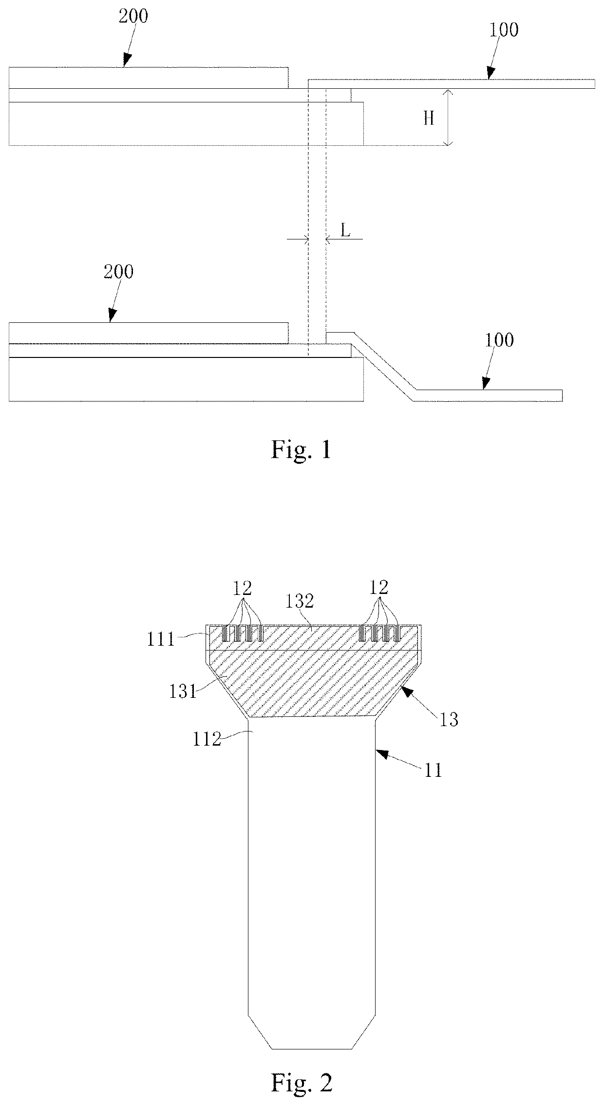
[0040]The inventor found by the long-term test that, when the flexible circuit board is laminated in the false pressure test process, the flexible circuit board may often shift, so that it is easy to cause the poor lamination of the electrically connected structure on the crimping portion of the flexible circuit board with the electrically connected structure on the crimping portion of the substrate to be tested, and even the misconnection and short-circuit case may occur, which severely affects the actual laminating effect and the test success rate. The inventor found after the research that, the reason why the flexible circuit board shifts is mainly the height offset H between the flexible circuit board 100 and the panel 200, as shown in FIG. 1. Due to the height offset H, in the laminating process, the flexible circuit board 100 is easy to bend and shift downward and thus the flexible circuit board 100 shifts relative to the preset laminating position by the offset L, which, on t...


PUM


Abstract

The present disclosure relates to the field of circuit testing technologies and discloses a flexible circuit board and a test fixture. The flexible circuit board comprises: a flexible body which has a first crimping portion and an extension portion, the first crimping portion being used to be laminated with a second crimping portion of a substrate to be tested; a first electrically connected structure which is located on a first side of the flexible body, arranged on the first crimping portion, and used to be laminated with a second electrically connected structure on the second crimping portion; a support structure which is located on the first side of the flexible body and includes a first support portion and a second support portion; the first support portion is arranged on the extension portion and configured to support the extension portion in the laminating state.

Description

[0001]This application claims the benefit of Chinese Patent Application No. 201910580657.2, filed with the Chinese Patent Office on Jun. 28, 2019, and entitled “Flexible circuit board and test fixture”, which is hereby incorporated by reference in its entirety.FIELD OF INVENTION[0002]The present disclosure relates to the field of circuit testing technologies, and particularly to a flexible circuit board and a test fixture.BACKGROUND[0003]Generally, the test method of the circuit unit visualization (Cell Visual) of the display panel product is as follows: the individual sub-pixels in the panel are connected with the common electrode (Vcom) respectively and then connected to the corresponding probe test terminals (Pad) on the panel respectively, the gate line (Gate) signals are connected to the test terminals on the panel in the same way, and then the corresponding signals are applied to the individual test terminals on the panel by pressing the probes thereon to enable the panel to d...

Claims


Application Information

Patent Timeline
Patent Type & Authority Applications(United States)
IPC IPC(8): H05K1/02H05K1/18G09G3/00
CPCG09G3/006G09G2330/12H05K2201/05H05K2201/09818H05K1/189H05K2201/10128H05K2201/02H05K1/0281H05K2201/09181H05K1/118G01R1/04G09G2380/02H05K1/0268H05K2203/167H05K1/028
Inventor XIA, HUIJIANXU, NING
Owner WUHAN TIANMA MICRO ELECTRONICS CO LTD
Why Eureka
Try Eureka