
Method of making surfaces smooth or flat for 3D printing

a 3d printing and surface technology, applied in the field of 3d printing, can solve problems such as deformation on tenacity film, and achieve the effect of reducing surface defects and improving the printing quality of physical models

Inactive Publication Date: 2020-03-05
XYZPRINTING +1
View PDF0 Cites 4 Cited by
  • Summary
  • Abstract
  • Description
  • Claims
  • Application Information

AI Technical Summary

Benefits of technology

The disclosed example is about a method to make surfaces smooth or flat for 3D printing. This method can reduce or eliminate deformation on the tenacity film, which improves the printing quality of physical models and reduces defects on the surface.

Problems solved by technology

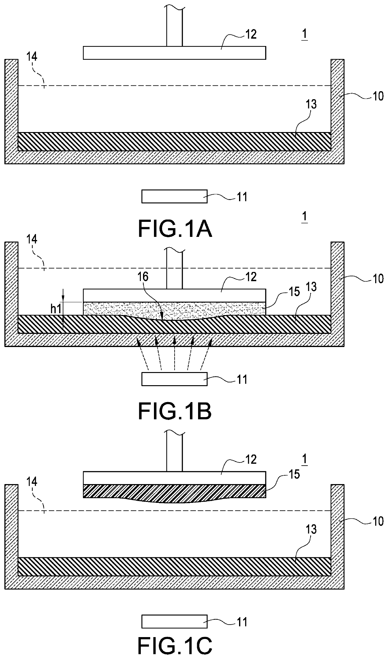
However, a deformation may occur on the tenacity film when the tenacity film is pressed by a force.

Method used


Image

  • Method of making surfaces smooth or flat for 3D printing
  • Method of making surfaces smooth or flat for 3D printing
  • Method of making surfaces smooth or flat for 3D printing

Examples


first embodiment

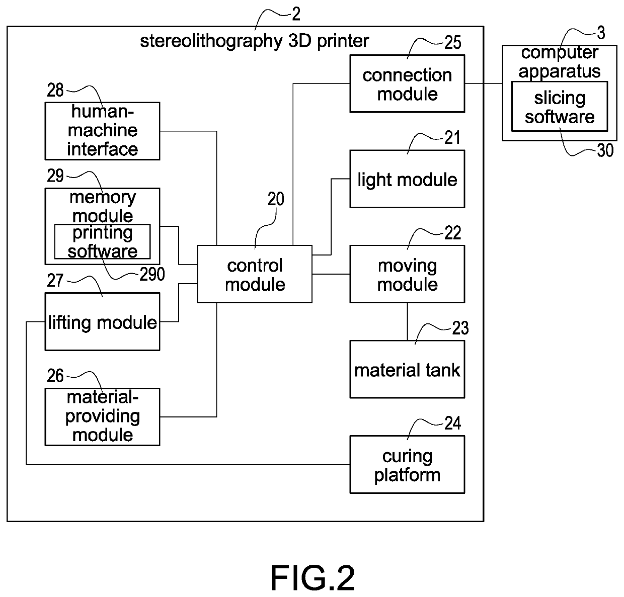
[0045]Please refer to FIG. 4A to FIG. 6, FIG. 4A is a first schematic view of stereolithography 3D printing according to one embodiment of the present disclosed example, FIG. 4B is a second schematic view of stereolithography 3D printing according to one embodiment of the present disclosed example, FIG. 4C is a third schematic view of stereolithography 3D printing according to one embodiment of the present disclosed example, FIG. 4D is a forth schematic view of stereolithography 3D printing according to one embodiment of the present disclosed example, FIG. 5 is a schematic view of appearance of a 3D printer according to one embodiment of the present disclosed example and FIG. 6 is a flowchart of a method of making surfaces smooth or flat for 3D printing according to the present disclosed example.

[0046]The stereolithography 3D printer 2 shown in FIG. 4A to FIG. 4D is configured to move the material tank 23 by moving horizontally. The stereolithography 3D printer 2 shown in FIG. 5 is ...

second embodiment

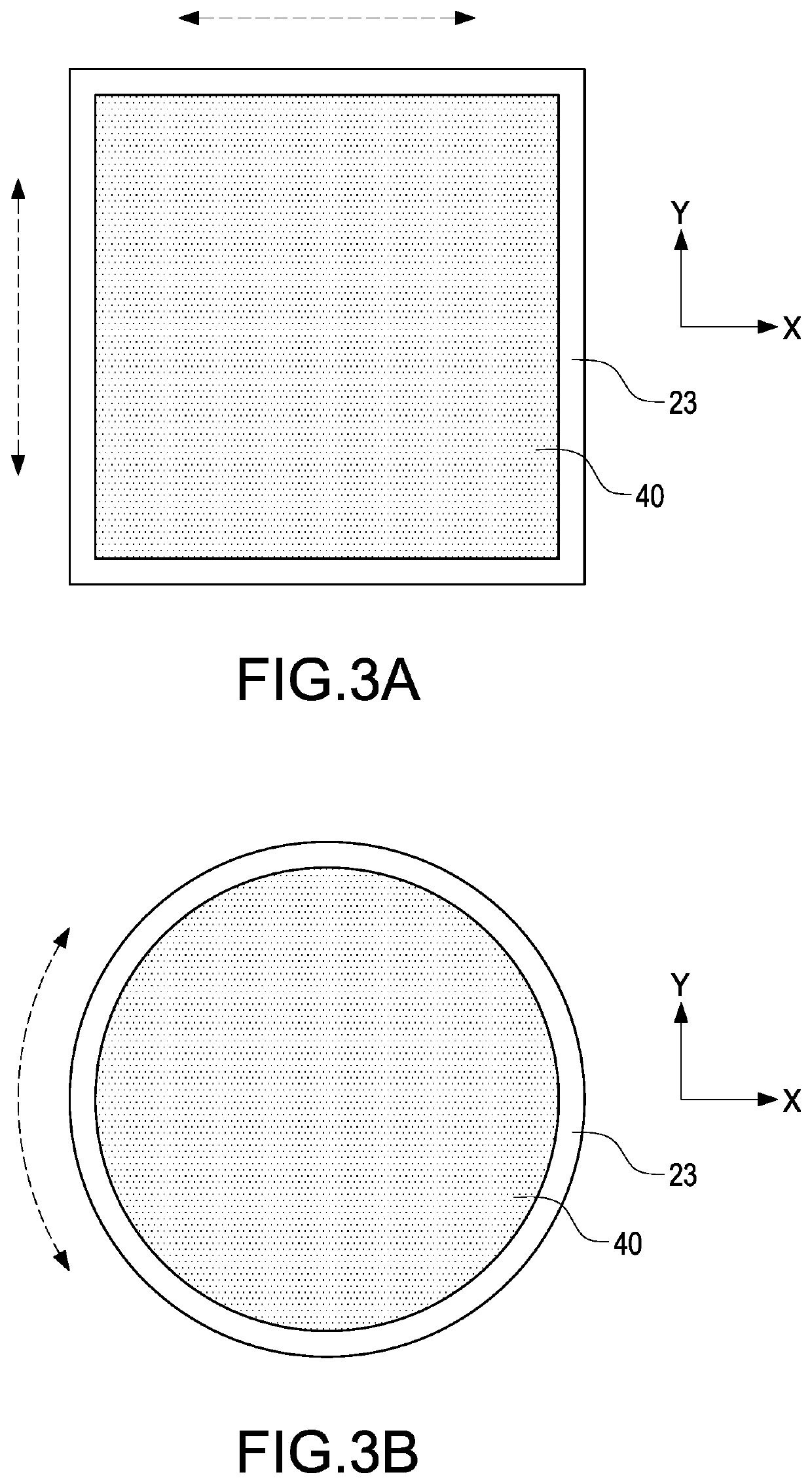
[0066]Please refer to FIG. 7 simultaneously, FIG. 7 is a flowchart of a method of making surfaces smooth or flat for 3D printing according to the present disclosed example. This embodiment uses the moving means that rotation as shown in FIG. 3B, but this specific example is not intended to limit the scope of the present disclosed example. The moving means may be replaced with horizontal movement as shown in FIG. 3A and FIG. 4A in the other embodiment. Moreover, this embodiment takes the stereolithography 3D printer 2 of FIG. 2 and FIG. 5 for explain. More specifically, after reception of a 3D printing instruction (such as receiving the printing data and the 3D printing instruction from the computer apparatus 3), the stereolithography 3D printer 2 may perform following steps for manufacturing a 3D physical model corresponding to above-mentioned print data.

[0067]Step S20: the control module 20 of the stereolithography 3D printer 2 determines whether a default condition to supply for r...


PUM

PropertyMeasurementUnit
thickness h2aaaaaaaaaa
angleaaaaaaaaaa
timeaaaaaaaaaa

Abstract

A method of making surfaces smooth or flat for 3D printing applied to a stereolithography 3D printer (2) is provided. The method is to control a modeling plane of a curing platform (24) to contact light-curable materials (41) in a material tank (23), moving the modeling tank (23) by a moving module (22) for making the light-curable materials (41) in the modeling tank (23) flow, and control a light module (21) to irradiate the curing platform (24) according to print data for manufacturing one layer of slice physical model on the modeling plane. The method can effectively reduce the defects on the surface of a physical model, and improve a printing quality of the physical models.

Description

BACKGROUND OF THE INVENTIONField of the Invention[0001]The technical field relates to 3D printing and more particularly related to a method of making surfaces smooth or flat for 3D printing.Description of Related Art[0002]A stereolithography 3D printer of the related art has an ability to cure the light-curable materials into a 3D physical model by light-irradiating. More specifically, the stereolithography 3D printer comprises a curing platform, a material tank, and a light module. The material tank is used to accommodate the fluid light-curable materials, and a tenacity film is laid on the bottom of the material tank. A surface of above-mentioned tenacity film is very smooth, so as to make the cured light-curable materials (namely 3D physical model) do not stick to the tenacity film and prevent the printing from failure.[0003]However, a deformation may occur on the tenacity film when the tenacity film is pressed by a force. For example, when the curing platform submerge into the l...

Claims


Application Information

Patent Timeline
Patent Type & Authority Applications(United States)
IPC IPC(8): B29C64/135G03F7/20
CPCG03F7/70416B29C64/135B33Y30/00B33Y40/00B33Y70/00B33Y50/02B33Y10/00B29C64/124B29C64/30B29C64/20B29C64/321
Inventor CHOU, CHING-YUAN
Owner XYZPRINTING
Learn More