
Circuit carrier with embedded substrate, manufacturing method thereof and chip package structure

a technology of embedded substrates and circuit carriers, which is applied in the direction of electrical equipment, semiconductor devices, semiconductor/solid-state device details, etc., can solve the problems of limiting the size of the chip package structure and reducing the z-axis height of the overall chip package structure, so as to achieve a thinner package thickness, reduce the volume of the package, and reduce the size of the packag

Active Publication Date: 2020-03-05
UNIMICRON TECH CORP
View PDF12 Cites 1 Cited by
  • Summary
  • Abstract
  • Description
  • Claims
  • Application Information

AI Technical Summary

Benefits of technology

The present invention provides a method for manufacturing a circuit carrier with embedded substrate that can integrate multiple components in a thin and compact design. The manufacturing process includes a trench where the embedded substrate is placed, and the chips are connected to the circuit structure and embedded substrate through bumps. This design allows for a thinner and flatter circuit carrier that can be used in smaller packaging. Overall, the invention allows for a more efficient use of space and a more compact and high-performance chip package design.

Problems solved by technology

However, with the consumer's demand for miniaturization and thinning of electronic products, disposing interposers on the circuit carrier limits the size of the chip package structure, especially the Z-axis height of the overall chip package structure.
Therefore, how to effectively reduce the Z-axis height of the overall chip package structure is a problem to be solved in the field.

Method used


Image

  • Circuit carrier with embedded substrate, manufacturing method thereof and chip package structure
  • Circuit carrier with embedded substrate, manufacturing method thereof and chip package structure
  • Circuit carrier with embedded substrate, manufacturing method thereof and chip package structure

Examples


Embodiment Construction

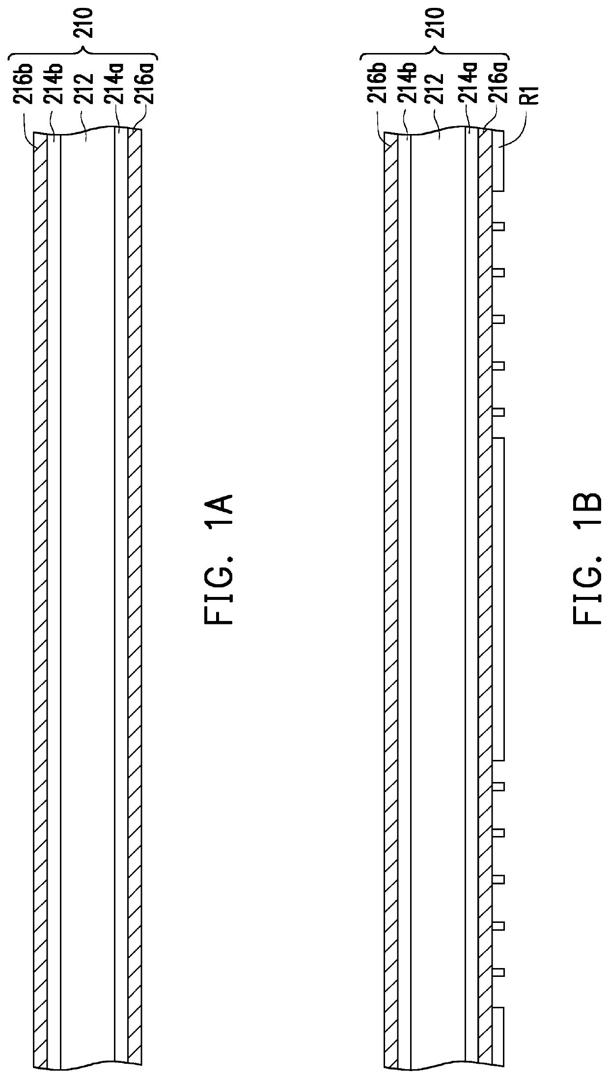
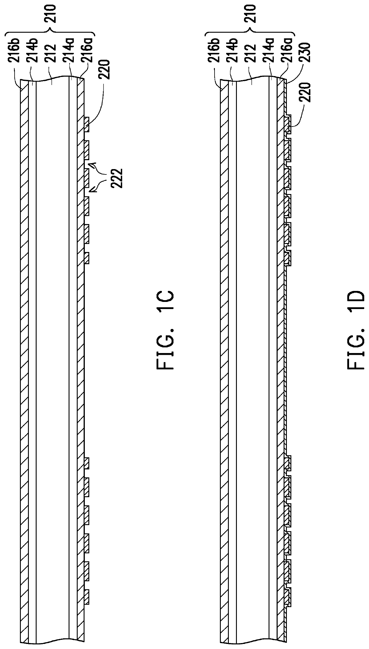
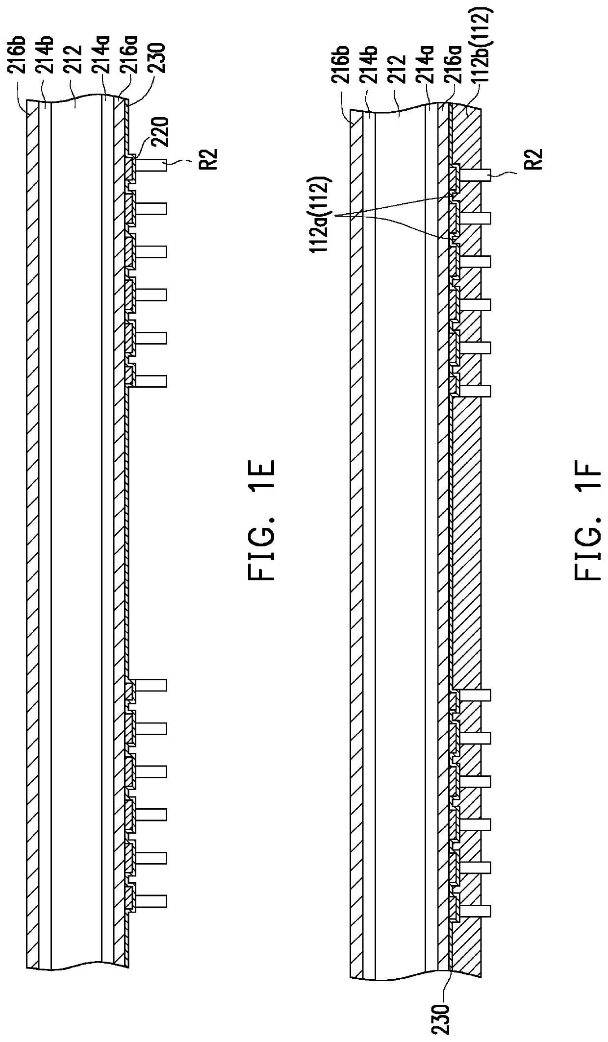
[0027]FIG. 1A to FIG. 1M are schematic cross-sectional diagrams showing a method of fabricating a circuit carrier with embedded substrate according to an embodiment of this invention. Referring first to FIG. 1J, a circuit structure 110 is first provided in this embodiment.

[0028]In detail, referring to FIG. 1A, a core layer 210 is provided, wherein the core layer 210 includes a core dielectric layer 212, at least one release layer 214a and 214b (shown schematically as two layers in FIG. 1A), and at least one copper foil layer 216a and 216b (shown schematically as 2 layers in FIG. 1A).

[0029]Next, referring to FIG. 1B and FIG. 1C, a first patterned copper layer 220 is formed on the copper foil layer 216a. In this embodiment, the step of forming the first patterned copper layer 220 on the copper foil layer 216a is as follows. First, a first patterned photoresist layer R1 is formed on the copper foil layer 216a. Next, a first cooper layer is formed on the first patterned photoresist laye...


PUM

PropertyMeasurementUnit
conductiveaaaaaaaaaa
dielectricaaaaaaaaaa
circuit structureaaaaaaaaaa

Abstract

A circuit carrier with embedded substrate includes a circuit structure and an embedded substrate. The circuit structure includes a first dielectric layer, a first patterned circuit layer, a trench, and a plurality of first bumps. The first dielectric layer has a first surface and a second surface opposite to each other. The first patterned circuit layer is embedded in the first surface. The first bumps are disposed on the first surface and electrically connected to the first patterned circuit layer. The trench exposes a portion of the first dielectric layer. The embedded substrate is disposed in the trench and includes a plurality of second bumps. A chip package structure includes the above circuit carrier with embedded substrate.

Description

CROSS-REFERENCE TO RELATED APPLICATION[0001]This application claims the priority benefit of Taiwan application serial no. 107130470, filed on Aug. 31, 2018. The entirety of the above-mentioned patent application is hereby incorporated by reference herein and made a part of this specification.BACKGROUND1. Field of the Invention[0002]This invention relates to a circuit carrier, a manufacturing method thereof and a package structure, and particularly to a circuit carrier with embedded substrate, a manufacturing method thereof and a chip package structure.2. Description of Related Art[0003]Currently, in a package structure having a plurality of interconnected chips, interposers are often used as a bridging element to connect different chips and to dispose the chips on a circuit carrier. However, with the consumer's demand for miniaturization and thinning of electronic products, disposing interposers on the circuit carrier limits the size of the chip package structure, especially the Z-a...

Claims


Application Information

Patent Timeline
Patent Type & Authority Applications(United States)
IPC IPC(8): H01L23/498H01L21/768H01L23/00H01L23/532
CPCH01L23/49822H01L23/53233H01L23/49816H01L21/76816H01L24/17H01L2924/15153H01L2224/32225H01L2224/12105H01L2224/16227H01L2224/16145H01L2224/73267H01L2924/15313H01L2224/92244H01L2224/131H01L24/13H01L24/16H01L24/73H01L24/32H01L24/92H01L23/5384H01L23/5383H01L21/4857H01L21/486H01L23/5385H01L2924/014H01L2924/00014H01L24/27
Inventor LIN, CHIEN-CHENWANG, TZU-HSUANFONG, KUAN-WEN
Owner UNIMICRON TECH CORP
Learn More