Robot for performing droplet jetting and droplet jetting control method for robot

a robot and droplet technology, applied in the field of robots for dropping droplets, can solve the problems of affecting the efficiency and quality of mass production of products, the equipment available on the market for dropping droplets to form patterns freely, etc., and achieve the effects of simple spraying effect, flexible operation, and free movemen

Inactive Publication Date: 2020-03-12
SHAANXI HWATEC TECH CO LTD
View PDF0 Cites 0 Cited by
  • Summary
  • Abstract
  • Description
  • Claims
  • Application Information

AI Technical Summary

Benefits of technology

The present invention provides a robot for droplet jetting that can create micro droplets on both planar and three-dimensional products with free forming, small size, wide working range, and extensive adaptability. The robot can easily apply graphics and characters on objects without any dead angles. The pneumatic balance system allows for freer change in nozzle posture between high and low pitches, and the droplet jetting nozzle system can produce precise spraying in microlitre or nanolitre orders of magnitude. The robot is suitable for various applications such as production of complex electronic circuit, special medical reagent point sampling, special chemical reagent point sampling, fine chemical synthesis, etc.

Problems solved by technology

However, there is no equipment available on the market for droplet jetting to form patterns freely on the surface of an existing product.
Even if there are some equipments, they can only perform vertical jetting, being linked in X-Y plane only, but the facades or curved surfaces are mostly colored, spotted, and bonded manually, which affects the efficiency and quality of mass production of the product, because the demand for droplet jetting to form patterns freely on any curved surfaces has been very urgent in recent years.

Method used


Image

  • Robot for performing droplet jetting and droplet jetting control method for robot
  • Robot for performing droplet jetting and droplet jetting control method for robot
  • Robot for performing droplet jetting and droplet jetting control method for robot

Examples


example 1

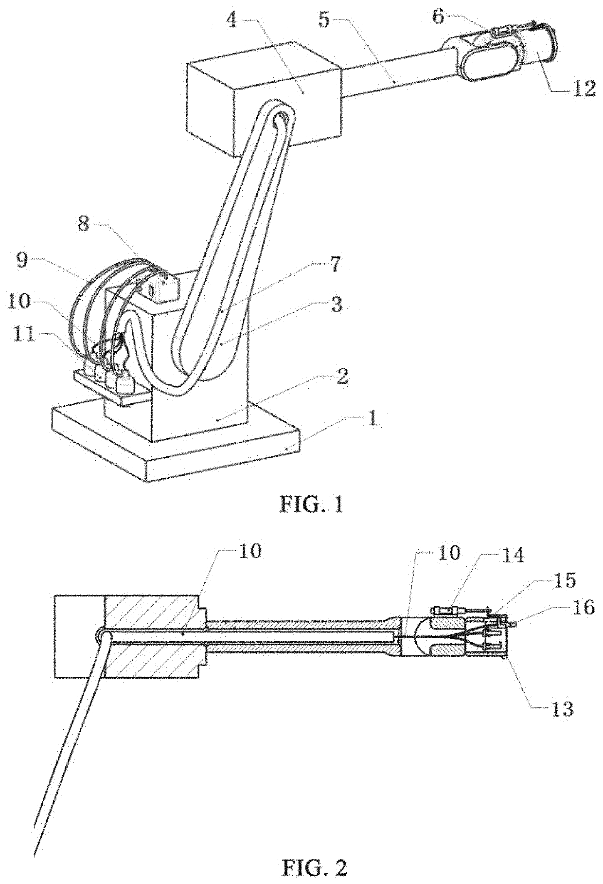
[0036]The robot for droplet jetting in this example comprises a control system, a mechanical motion structure, a droplet jetting system, and a pneumatic balance system; wherein the control system synchronously performs motion control and droplet jetting control.

[0037]As shown in FIGS. 1-2, the mechanical motion structure comprises abase 1, a rotary seat 2, a swing arm 3, a swing arm 4, a rotary arm 5, and a swing arm 6. The base may be equipped with a rotary worktable or a movable slide rail as needed. The rotary seat 2 is arranged on the base 1 and freely rotatable about a longitudinal axis; the swing arm 3 is arranged on the rotary seat 1 and free to swing around a connection point; the swing arm 4 is arranged at the other end of the swing arm 3 and free to swing around a connection point; the rotary arm 5 is arranged on the swing arm 4 and rotatable freely about the normal axis of a contact surface; the swing arm 6 is arranged on the rotary arm 5 and free to swing around a connec...

example 2

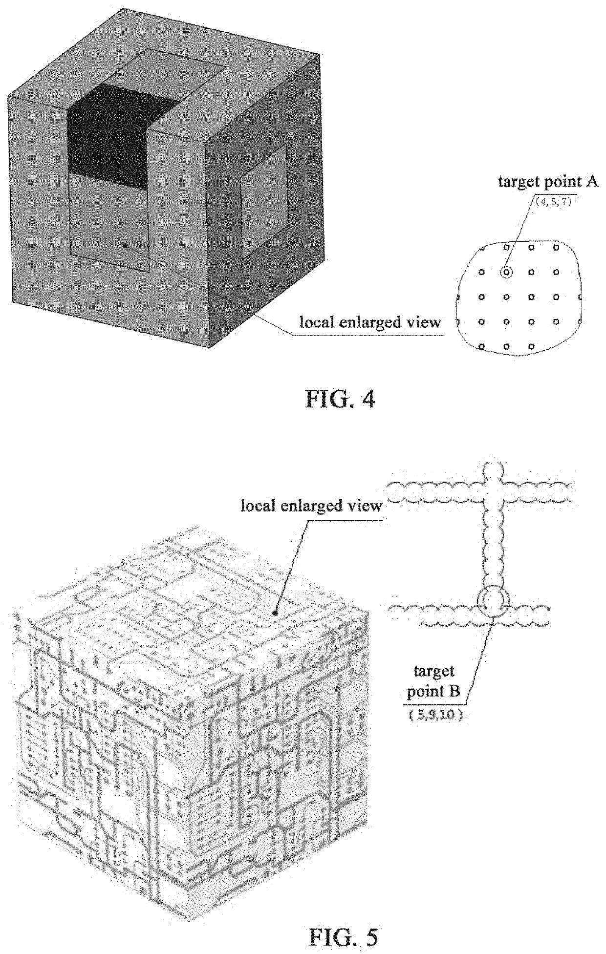
[0042]In this embodiment, colors are sprayed onto the image shown in FIG. 4, and four colors, CMYK, are filled in four nozzles respectively. The control method is as follows:

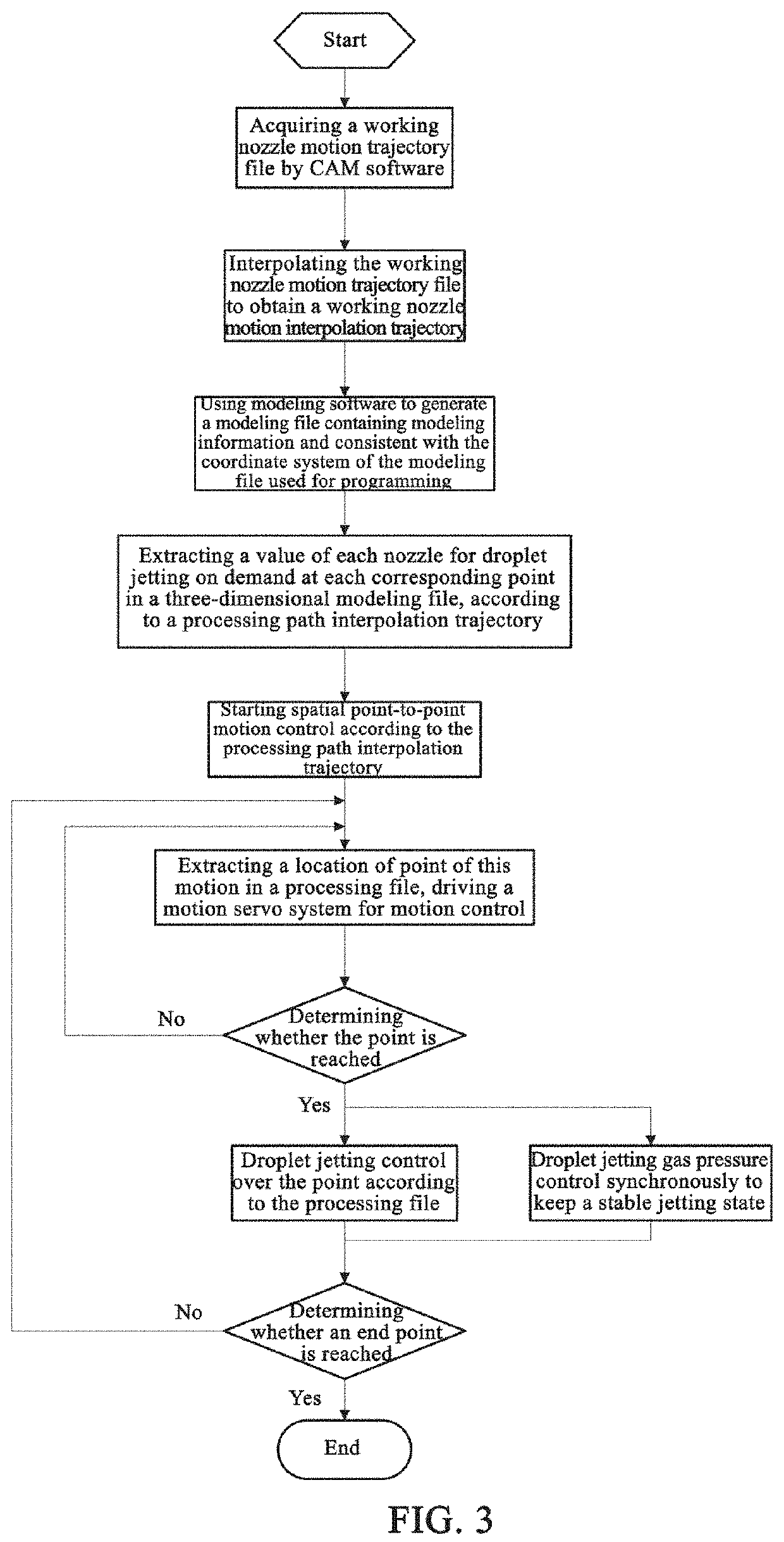
[0043]Referring to FIG. 3, the entire control process is a point-by-point jetting process, such as any point A shown in FIG. 4:

[0044]Step 1: generating a processing file:

[0045]The processing file includes a working nozzle motion interpolation trajectory, and color information corresponding to each point in the working nozzle motion interpolation trajectory:

[0046](1) A CAM software (such as UG) is used to program FIG. 4 to be sprayed to obtain a working nozzle motion trajectory file which is then interpolated to obtain the working nozzle motion interpolation trajectory;

[0047](2) A modeling software (such as 3D MAX) is used to generate a modeling file containing the color information of FIG. 4 (this modeling file is consistent with the coordinate system of the file used for programming);

[0048](3) The color informa...

example 3

[0054]In this example, a conductive solution is sprayed onto a circuit board, and a conductive material (CNT suspension) and an insulating material (impregnating paint) are respectively contained in two nozzles.

[0055]Step 1: generating a processing file:

[0056]The processing file includes a working nozzle motion interpolation trajectory, and the material information (which refers to the conductive material or the insulating material) corresponding to each point in the working nozzle motion interpolation trajectory:

[0057](1) A CAM software (such as UG) is used to program FIG. 5 to be sprayed to obtain a working nozzle motion trajectory file which is then interpolated to obtain the working nozzle motion interpolation trajectory;

[0058](2) A modeling software (such as 3D MAX) is used to generate a modeling file containing the material information of FIG. 5 (this modeling file is consistent with the coordinate system of the file used for programming);

[0059](3) The material information of ...


PUM


Abstract

Provided are a robot for performing droplet jetting, and a droplet jetting control method for a robot. The robot for performing droplet jetting comprises a control system, a mechanical motion structure, a droplet jetting system, and an aerodynamic balance system. The control system implements motion control and droplet jetting control. The mechanical motion structure is a multi-degree-of-freedom mechanical structure and is used to implement a multi-degree-of-freedom motion function. The droplet jetting system is installed at the mechanical motion structure. The aerodynamic balance control system controls, according to a change in an air pressure of a nozzle, air pressures inside and outside of the nozzle to attain a balance so as to ensure a stable jetting, thereby preventing jetting of an excessive amount or an insufficient amount of droplets. The robot for performing droplet jetting can realize freer fabrication of products having planar and curved surfaces without any dead angles by performing omni-directional micro-droplet jetting.

Description

TECHNICAL FIELD[0001]The invention belongs to droplet jetting fields, and specifically relates to a robot for droplet jetting, capable of realizing droplet jetting function on any three-dimensional object by feeding material on demandBACKGROUND ART[0002]Droplet jetting is to propel a forming material with an external force to be sprayed from an orifice (nozzle) of a nozzle cavity onto a substrate in the form of a fine droplet (or a liquid flow), thereby forming two-dimensional images (words), dot arrays or three-dimensional objects. The term “fine droplet” refers to an ejected droplet with a size that can be precisely controlled in a micron order of magnitude, and with a volume that can be controlled in a microlitre, or a nanolitre, or a picolitre order of magnitude, or even a femto-litre order of magnitude. For currently available droplet jetting technologies, plane-based droplet jetting such as inkjet printing, 3D printing has become a relatively matured technology. For example, d...

Claims


Application Information

Patent Timeline
Patent Type & Authority Applications(United States)
IPC IPC(8): B05B13/04B05B12/00
CPCB05B14/00B05B13/0278B05B13/0431B05D1/02B05B13/041B25J9/00B05B12/00B05B13/04B05B9/04B05B12/085B25J19/0029B41J3/4073B05B15/16B05B15/72
Inventor SHI, YIYANG, FUTAOHUANG, XINZHU, CHENHUI
Owner SHAANXI HWATEC TECH CO LTD
Why Eureka
Try Eureka