Vortex tube lined with magnets and uses thereof

a vortex tube and magnet technology, applied in the field of vortex tubes lined with magnets, can solve the problems of complexity, associated cost, direct impact on aerospace and medical industries, etc., and achieve the effect of increasing the separation performance of the vortex tube and cost effectiv

Active Publication Date: 2020-03-19
WASHINGTON STATE UNIVERSITY
View PDF0 Cites 5 Cited by
  • Summary
  • Abstract
  • Description
  • Claims
  • Application Information

AI Technical Summary

Benefits of technology

[0011]Accordingly, the embodiments herein provide for an apparatus and a system of purifying gas mixtures that exploit the benefits of using a magnetic field gradient for separating desired paramagnetic molecular and / or atomic species from the gas mixture. The system herein is cost effective and increases the separation performance of a vortex tube for air, even at room temperature with respect to conventional systems.

Problems solved by technology

The cost of oxygen separation is a key barrier towards localized and efficient oxygen production which directly affects the aerospace and medical industries.
Such a system and method, however, does have a disadvantage of complexity and associated cost, such as the large size of the gravity-based cryogenic distillation columns.
LOX purity has been further increased to 97% by applying controlled heating power over liquid oxygen flowing discharge surface of the vortex tube.” However, while such use of vortex tubes is beneficial in separating out, in particular, liquid oxygen, the art cited above does not capitalize on separating a number of molecular species of interest having paramagnetic properties in combination with the beneficial aspects of vortex tube effects.

Method used


Image

  • Vortex tube lined with magnets and uses thereof
  • Vortex tube lined with magnets and uses thereof
  • Vortex tube lined with magnets and uses thereof

Examples


example

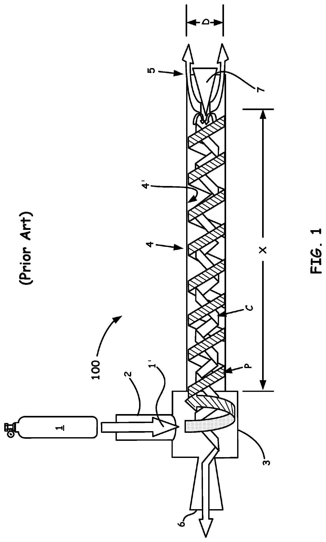
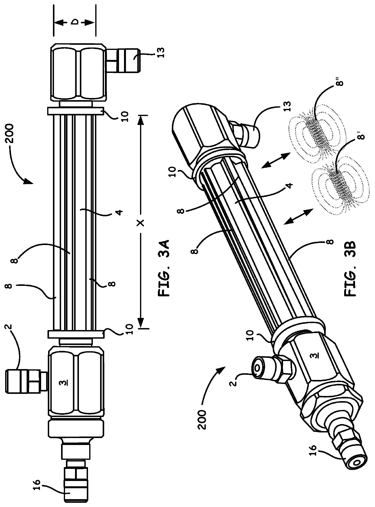
[0041]An experiment was implemented that allowed for oxygen separation through a vortex tube, as now shown in FIG. 5 and as generally referenced by the numeral 500, so as to be monitored both with and without an applied magnetic field gradient. The selected vortex tube 4 was a counter-flow Vortec model with a 1-cm internal diameter. Six 1.5-Tesla N52 rare-earth bar magnets 8 with lengthwise poles were coupled in a removable fashion with alternating polarity, as described above, to the vortex tube 4 with a 3D printed fixture, i.e., using a retainer ring 10 as the coupling mechanism. The fixture positions the magnetic components 8 along the periphery of the vortex tube 4 in an example cone-shape such that the magnets are in contact at the entrance (i.e., adjacent inlet 2, spin generator 3, and the proximate (cold) end 16) of the vortex tube centrifuge and held at a non-limiting distance at the end of the periphery outlet (i.e., adjacent the hot distal end 13, as shown in FIG. 5).

[0042...


PUM

PropertyMeasurementUnit
inlet pressureaaaaaaaaaa
inlet temperatureaaaaaaaaaa
diameteraaaaaaaaaa

Abstract

A magnetic/energetic apparatus for purifying gas mixtures comprises a vortex tube and magnetic elements. Such an apparatus can include an inlet valve configured to receive a gas mixture having one or more disposed paramagnetic gas species and one or more diamagnetic gas species; a high-shear environment energetic separation chamber coupled to the inlet valve; a plurality of magnetic elements coupled to an outer wall of the high-shear environment separation chamber, wherein each of the plurality of magnetic elements are arranged so as to have a respective pole alternating in polarity with respect to an adjacently positioned magnetic element so as to induce a field gradient between each of the adjacently positioned magnetic elements and within the inner wall of the high-shear environment separation chamber; and at least one exit valve so as provide a substantially separated one or more paramagnetic gas species from the one or more diamagnetic gas species.

Description

CROSS-REFERENCE TO RELATED APPLICATION(S)[0001]The present application claims under 35 U.S.C. § 119, the priority benefit of U.S. Provisional Application No. 62 / 731,226, filed Sep. 14, 2018, entitled “VORTEX TUBE LINED WITH MAGNETS AND USES THEREOF,” of which is incorporated herein by reference in its entirety.BACKGROUND OF THE INVENTIONField of the Invention[0002]The present embodiments herein relate to separating out complex mixture of gases. In particular, the present system / apparatus and method embodiments disclosed herein are directed to centrifugal and magnetic separation of paramagnetic molecular and / or atomic species, such as, but not limited to, oxygen, using magnetic configurations in combination with a vortex tube.Discussion of the Related Art[0003]The cost of oxygen separation is a key barrier towards localized and efficient oxygen production which directly affects the aerospace and medical industries. There have been two major fundamental approaches of air separation: c...

Claims


Application Information

Patent Timeline
Patent Type & Authority Applications(United States)
IPC IPC(8): B01D53/24B03C1/14B03C1/033H01F7/02
CPCB01D53/24B03C2201/16B03C1/0337B03C1/14H01F7/02H01F7/0294H01F6/00B03C1/0332B03C1/0335B03C1/288B01D2257/104B01D53/00B01D2259/814
Inventor LEACHMAN, JACOBBUNGE, CARLRAYMOND, JORDAN
Owner WASHINGTON STATE UNIVERSITY
Why Eureka
Try Eureka