Vehicle Suspension
a technology for suspensions and vehicles, applied in the direction of suspension arms with pivoting arms, monocoque constructions, transportation and packaging, etc., to achieve the effects of facilitating maintenance, reducing engine-generated heat loads, and strong configuration
- Summary
- Abstract
- Description
- Claims
- Application Information
AI Technical Summary
Benefits of technology
Problems solved by technology
Method used
Image
Examples
case 1
[0084] Single Wheel Compression
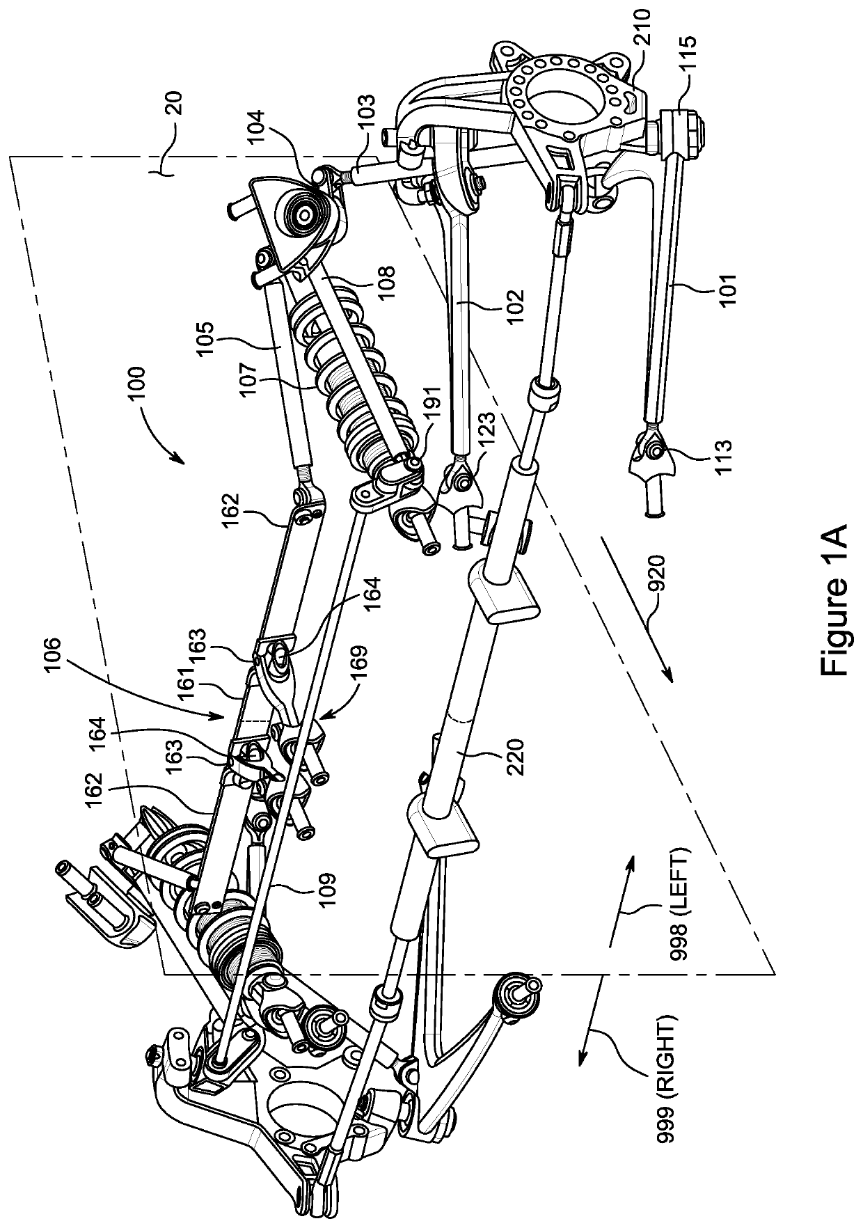
[0085]In the single wheel compression scenario, illustrated in FIG. 11, it is assumed that wheel hub 210L is subject to a displacement in the upward direction relative to chassis 15. At the same time, it is assumed that a comparable displacement does not take place for the right wheel hub 210R. The single wheel compression scenario can arise, for example, when the wheel mounted to wheel hub 210L hits a bump in the road causing that wheel to rise relative to chassis 15.
[0086]In this single wheel compression scenario, the upward displacement of wheel hub 210L relative to chassis 15 causes upward displacement, relative to chassis 15, of lower control arm 101L proximate its apex portion 112L. This upward displacement causes main pushrod 103L to be displaced, which in turn rotates bell crank 104L about shaft 141L. Rotation of bell crank 104L compresses coil over shock absorber 107L, thereby attenuating the upward movement of wheel hub 210L. The rotation of ...
case 2
[0088] Single Wheel Extension
[0089]In the single wheel extension scenario, illustrated in FIG. 12, it is assumed that wheel hub 210L is subject to a displacement in the downward direction relative to chassis 15. At the same time, it is assumed that a comparable displacement does not take place for the right wheel hub 210R. This load scenario can arise, for example, when the tire mounted to wheel hub 210L encounters a pothole in the road that causes that wheel to drop relative to the chassis.
[0090]In this single wheel extension scenario, the downward displacement of wheel hub 210L relative to chassis 15 causes downward displacement, relative to chassis 15, of lower control arm 101L proximate its apex portion 112L. This downward displacement causes main pushrod 103L to be displaced, which in turn rotates bell crank 104L about shaft 141L. Rotation of bell crank 104L extends coil over shock absorber 107L. Rotation of bell crank 104L additionally causes the rearward displacement of anti-...
case 3
[0092] Two Wheel Compression—Extension
[0093]In the two wheel compression—extension scenario, it is assumed that chassis 15 proximate to wheel hub 210L is subject to forces urging that region of chassis 15 in the downward direction, and that simultaneously chassis 15 proximate to wheel hub 210R is subject to forces urging that region of chassis 15 in the upward direction.
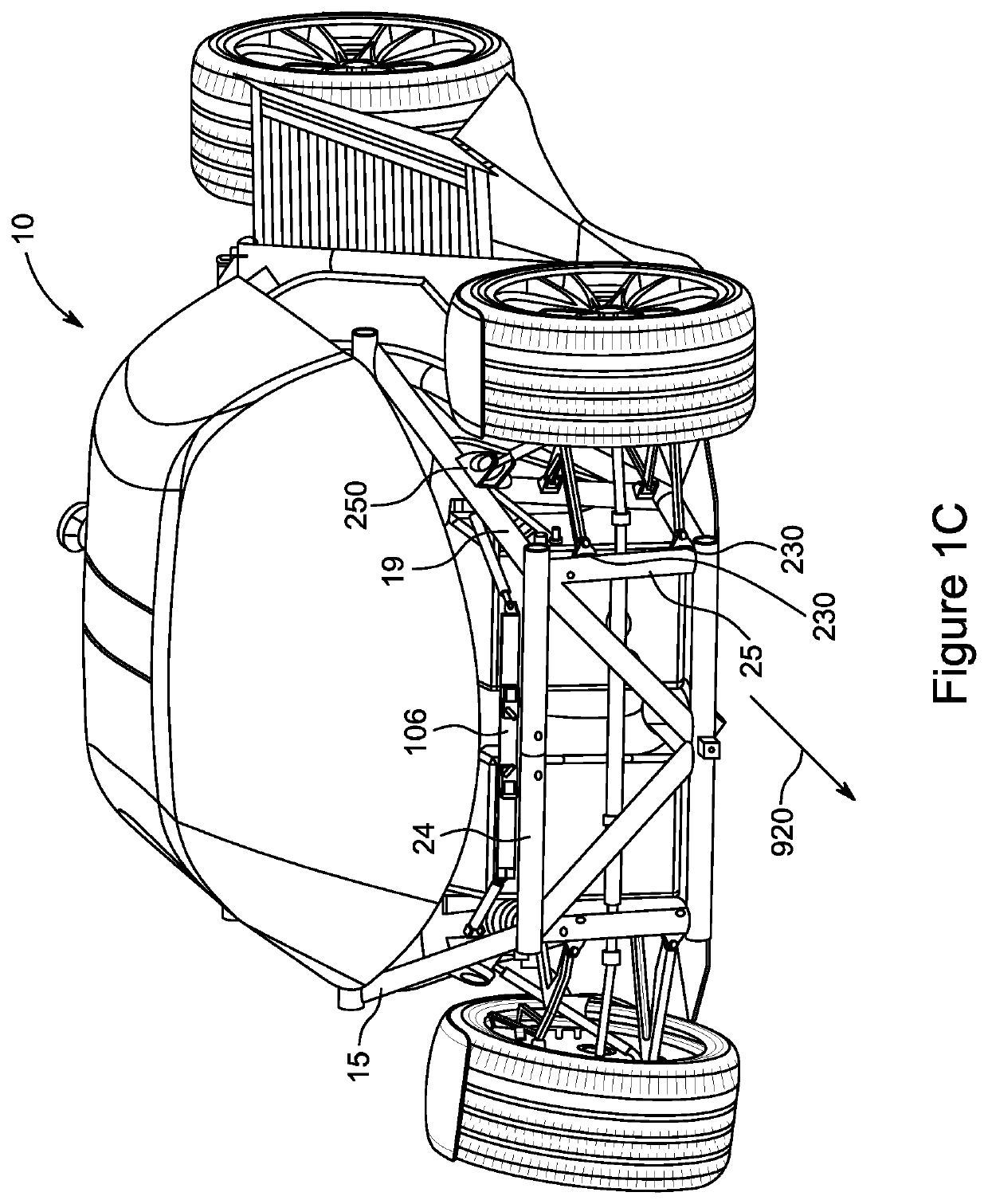
[0094]This two wheel compression—extension scenario can arise when vehicle 10 makes a turn at higher speeds, such as a turn to the right (see nomenclature of FIG. 1A) for purposes of this example. During such a turn, the wheel hub 210L is on the outside of the turn and the center of mass of vehicle 10 is above the axes of the wheels, so such a turn imposes a vertical force, on the left side of vehicle chassis 15, in addition to the static vehicle weight borne by that side. At the same time, wheel hub 210R is on the inside of the turn, and the location of the center of mass above the axes of the wheels reduces the ver...
PUM
 Abstract
Description
Claims
Application Information
 - R&D
- Intellectual Property
- Life Sciences
- Materials
- Tech Scout
- Unparalleled Data Quality
- Higher Quality Content
- 60% Fewer Hallucinations
Browse by: Latest US Patents, China's latest patents, Technical Efficacy Thesaurus, Application Domain, Technology Topic, Popular Technical Reports.
© 2025 PatSnap. All rights reserved.Legal|Privacy policy|Modern Slavery Act Transparency Statement|Sitemap|About US| Contact US: help@patsnap.com


