Method for planning trajectory of vehicle

a vehicle and trajectory technology, applied in the direction of navigation, instruments, surveying and navigation, etc., can solve the problems of limited time for spotting and recognizing static reference points on the side of the road, difficulty in following directions, and inability to provide useful information to drivers unfamiliar with the street name, so as to reduce the time needed for data processing, facilitate maintenance, and provide processing power.

Inactive Publication Date: 2020-03-26
VISTEON GLOBAL TECH INC
View PDF0 Cites 5 Cited by
  • Summary
  • Abstract
  • Description
  • Claims
  • Application Information

AI Technical Summary

Benefits of technology

[0030]According to an aspect, the system may further comprise a server configured to communicate and exchange data with at least one of the routing unit, the sensor unit, the processing unit, the instruction unit, and the output unit. Data communication may be accomplished for example by means of a wireless network, such as a mobile data network. The server does not need to be a single centrally managed piece of hardware but may be implemented as a cloud computing network with the advantage of redundant components and simplified maintenance.
[0031]According to an aspect, the processing unit may be located at the server. Using a processing unit at the server may achieve the advantage of more easily providing more processing power than locally provided at the ego vehicle. On the other hand, tasks may also be divided between a processor at the server and a processor at the ego vehicle in order to decrease the time needed for data processing and to more efficiently use the available processing power.

Problems solved by technology

A typical instruction of a turn-by-run navigation system may include a command such as, “In three hundred meters, turn right into Elm Street.” However, for some drivers such instructions may be difficult to follow since correctly judging the distance may not be an easy task for untrained humans.
Moreover, the street name may not be useful information for a driver who is not familiar with the area.
However, using static objects as references for guiding a driver requires that these objects are visible and easily recognizable at all times. Furthermore, when driving, the available time for spotting and recognizing a static reference point on the side of the road is limited.

Method used


Image

  • Method for planning trajectory of vehicle
  • Method for planning trajectory of vehicle
  • Method for planning trajectory of vehicle

Examples


Embodiment Construction

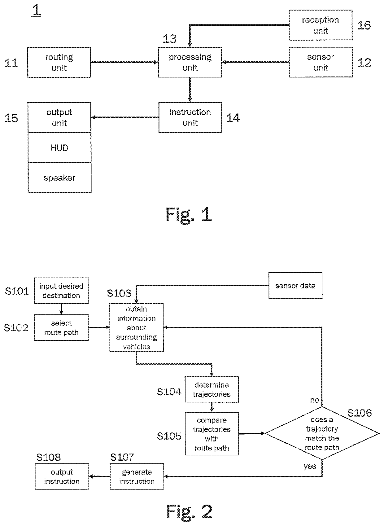
[0038]FIG. 1 shows a schematic illustration of a navigation system 1 for an ego vehicle according to an embodiment. The navigation system 1 may comprise a routing unit 11, a sensor unit 12, a processing unit 13, an instruction unit 14, an output unit 15, and a reception unit 16. The navigation system 1 may be implemented as part of an advanced driver-assistance system (ADAS) comprising an instrument cluster. In particular, the navigation system 1 may be used in motor vehicles such as an automobile, a motorcycle, or a truck. In some embodiments, the different units of the navigation system 1 may be implemented as software modules running on one or more electronic control units (ECUs). In particular, the sensor unit 12 and the routing unit 11 may run on different ECUs.

[0039]The routing unit 11 may enable the driver of the ego vehicle to select a route path for the ego vehicle to a desired destination. For this purpose, the routing unit 11 may comprise an input unit for receiving input...


PUM


Abstract

A method for operating a navigation system of an ego vehicle includes: obtaining information about vehicles in a region proximate the ego vehicle; determining trajectories of the vehicles proximate the ego vehicle based on the obtained information; comparing the trajectories of the vehicles proximate the ego vehicle with a selected route path of the ego vehicle; and based on a determination that at least one vehicle proximate the ego vehicle was driving, is currently driving, or will be driving along the selected route pate, generating and outputting an instruction to a driver of the ego vehicle to follow the at least one vehicle.

Description

CROSS-REFERENCES TO RELATED APPLICATIONS[0001]This patent application claims priority to European Patent Application Serial No. 18196059.2, filed Sep. 21, 2018, which is incorporated herein by reference in its entirety.TECHNICAL FIELD[0002]One or more embodiments described herein relate to a method for operating a navigation system for guiding a driver of an ego vehicle to a desired destination along a selected route path. In particular, the method may be implemented in a program, which is executed by a computer. Furthermore, one or more embodiments described herein relate to a navigation system for guiding a driver of an ego vehicle to a desired destination along a selected route path. Particularly, the navigation system may be part of, or work in conjunction with, an advanced driver-assistance system (ADAS).BACKGROUND[0003]In order to guide a driver of a vehicle to a specified goal along a selected route, most navigation systems use turn-by-turn navigation. Directions for followin...

Claims


Application Information

Patent Timeline
Patent Type & Authority Applications(United States)
IPC IPC(8): G01C21/36
CPCG01C21/3629G01C21/3691G01C21/3423G01C21/3632G01C21/3641G08G1/096791G08G1/096822
Inventor PFEIFLE, MARTINTORSCHMIED, AXELSCHRECK, CHRISTINEOTTO, MATTHIAS
Owner VISTEON GLOBAL TECH INC
Why Eureka
Try Eureka