Robust, low-cost capacitive measurement system

a capacitive measurement and low-cost technology, applied in the field of capacitive measurement circuits, can solve the problems easy disturbance of capacitive sensing devices, and achieve the effects of reducing the impact of a sense-to-guard impedance on the measurement accuracy, fast determination of the complex sense current, and less susceptibl

Active Publication Date: 2020-04-16
IEE INT ELECTRONICS & ENG SA
View PDF0 Cites 1 Cited by
  • Summary
  • Abstract
  • Description
  • Claims
  • Application Information

AI Technical Summary

Benefits of technology

[0015]It is therefore an object of the invention to provide a current measurement circuit of a capacitive sensing device that is less susceptible to interference by

Problems solved by technology

A challenging situation arises for capacitive sensing devices that are intended for vehicle applications and therefore have to comply with automotive rules and standards, for instance such as ISO 11451-4 (Road vehicles-Vehicle test

Method used


Image

  • Robust, low-cost capacitive measurement system
  • Robust, low-cost capacitive measurement system
  • Robust, low-cost capacitive measurement system

Examples


Embodiment Construction

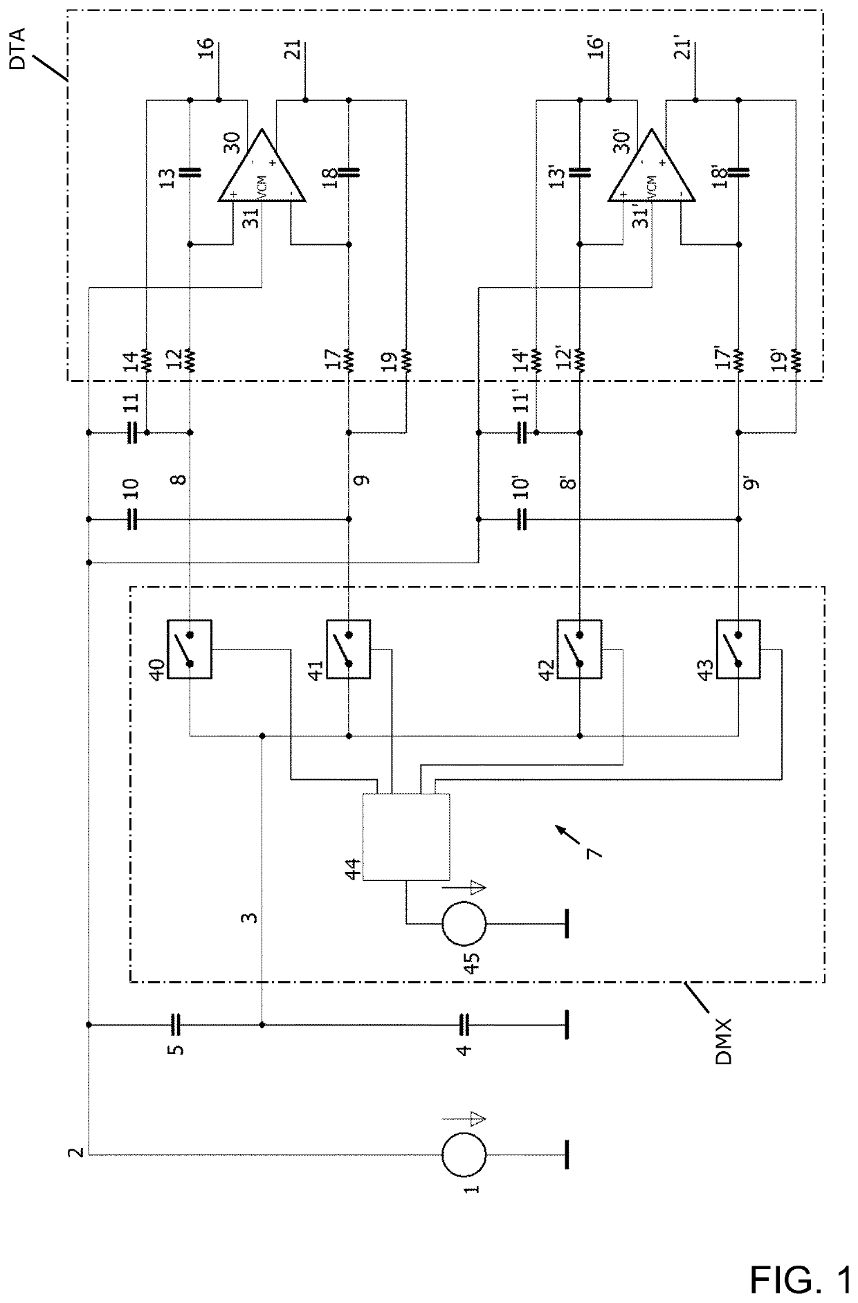
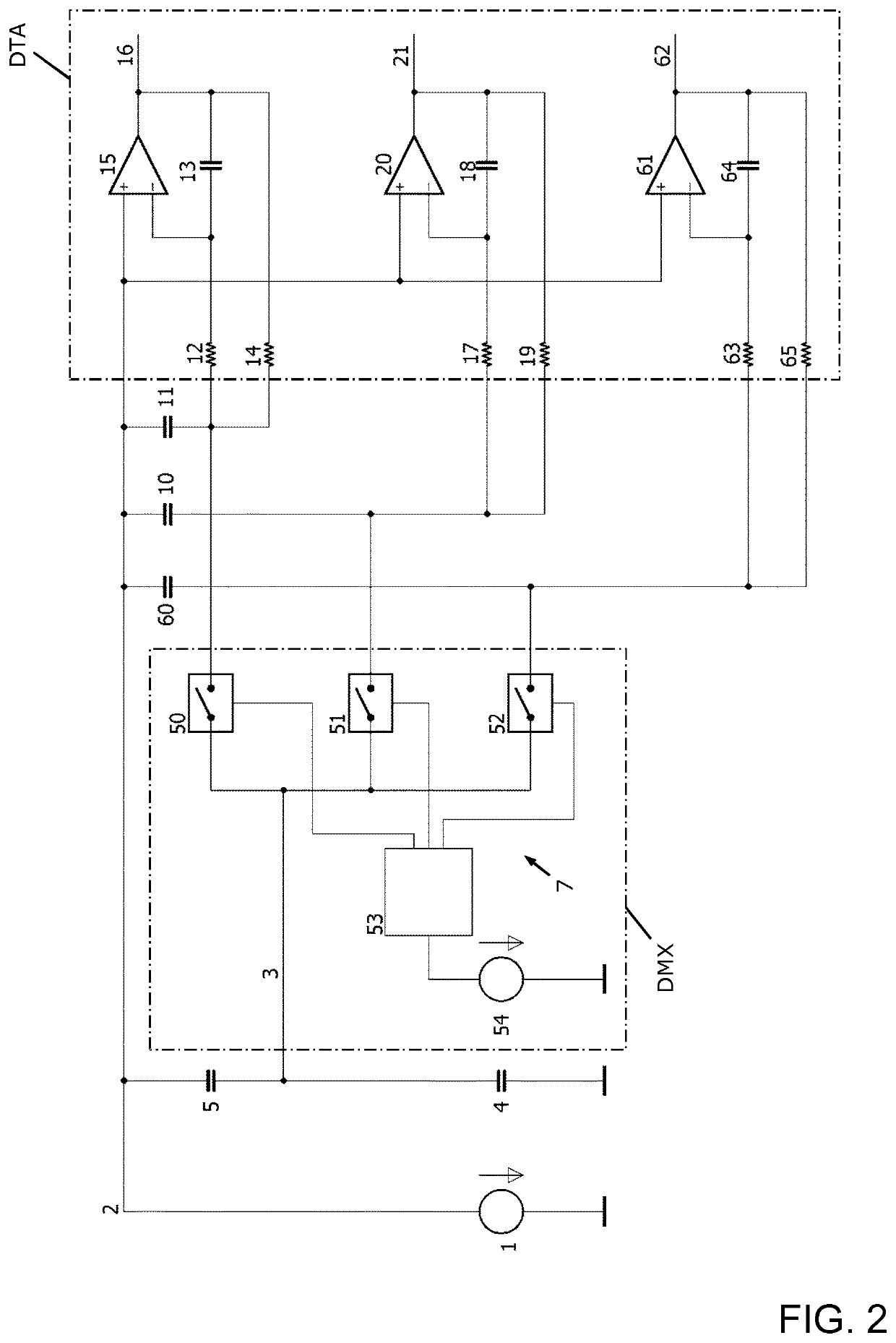
[0067]FIGS. 1 and 2 show layouts of possible embodiments of a complex current measurement circuit in accordance with the invention, configured to determine a complex sense current of a guard-sense capacitive sensor operated in loading mode.

[0068]The complex current measurement circuit comprises a periodic signal voltage source 1. It generates a periodic voltage, which in this specific embodiment is a sine wave with an operating or fundamental frequency between 10 kHz and 100 MHz, at an output port. The output port is electrically connected to a guard antenna electrode of the capacitive sensor at guard node 2.

[0069]The complex current measurement circuit further comprises a demultiplexer circuit DMX having a demultiplexer 7, a signal input line and a plurality of four signal output lines, and a differential transimpedance amplifier circuit DTA. The differential transimpedance amplifier circuit DTA includes four differential signal input lines 8, 8′, 9, 9′ and differential signal outp...


PUM


Abstract

A complex current measurement circuit for a guard-sense capacitive sensor includes a periodic signal voltage source, a differential transimpedance amplifier circuit (DTA) and a demultiplexer circuit (DMX). At least one sense antenna electrode of the capacitive sensor is electrically connectable to a signal input line of the DMX which has signal output lines electrically connected to differential signal input lines of the DTA. The DTA includes operational amplifiers having input ports each electrically connected to one of the signal output lines. For each differential signal input line, either a capacitor is electrically connected between an output port of the voltage source and the differential signal input line, wherein an impedance of the capacitor is close to zero Ohm, or a galvanic connection is provided to one of the signal output lines. An output signal provided by the DTA is usable for determining a complex sense current of the capacitive sensor.

Description

TECHNICAL FIELD[0001]The present invention generally relates to the technical field of capacitive measurement circuits and, more specifically, to a capacitive measurement device having one or more electrodes, by which characteristics such as shape and location of an object with a complex permittivity different from an environment are determined by means of capacitive coupling via the object.BACKGROUND OF THE INVENTION[0002]Capacitive sensors and capacitive measurement and / or detection devices employing capacitive sensors have a wide range of applications, and are among others used for the detection of the presence and / or the position of a conductive body in the vicinity of an antenna electrode. As used herein, the term “capacitive sensor” designates a sensor, which generates a signal responsive to the influence of what is being sensed (a person, a part of a person's body, a pet, an object, etc.) upon an electric field. A capacitive sensor generally comprises at least one antenna ele...

Claims


Application Information

Patent Timeline
IPC IPC(8): G01D5/24G01R19/00H03F3/45
CPCH03F2200/261G01R19/0092H03F3/45475H03F2203/45138G01D5/24H03K17/955H03K17/962H03F2203/45136H03F2203/45526H03K2217/960765H03K2217/960735
Inventor LAMESCH, LAURENT
Owner IEE INT ELECTRONICS & ENG SA
Why Eureka
Try Eureka