Raman immersion probe systems and methods

a technology of immersion probes and probes, applied in the field oframan spectroscopy, can solve the problems of interfering with the raman signal from the sample, slurries and solids, and laser safety is also an issue, so as to facilitate the path length adjustment and minimize cross-contamination

Active Publication Date: 2020-04-16
OWEN HARRY
View PDF0 Cites 1 Cited by
  • Summary
  • Abstract
  • Description
  • Claims
  • Application Information

AI Technical Summary

Benefits of technology

[0009]The proximal end of the second tube may be moveably sealed to the distal end of the first tube to facilitate path length adjustment of the counter-propagating excitation and collection beams. One or both of the tubes and associated optics may be disposable to minimize cross-contamination between maintenance or replacement. The baffled sample volume may be disposed within a process vessel or conduit to analyze a sample contained within or flowing through the vessel or conduit. The probehead may also be coupled to a microscope objective. The first and second tubes are cylindrical, with the diameter of the second cylindrical tube being greater than the diameter of the first cylindrical tube. As with the other embodiments disclosed herein, the system may further including a wavelength standard material supported in the counter-propagating excitation and collection beams.

Problems solved by technology

Despite the improvement, problems remain with slurries and solids.
Although distance, depth of field and phase boundary are well controlled, shorter focal lengths generate stronger Raman signals from the window material, potentially interfering with the Raman signal from the sample.
Laser safety is also an issue, as is the possibility of lased-induced fouling on the window.

Method used


Image

  • Raman immersion probe systems and methods
  • Raman immersion probe systems and methods
  • Raman immersion probe systems and methods

Examples


Embodiment Construction

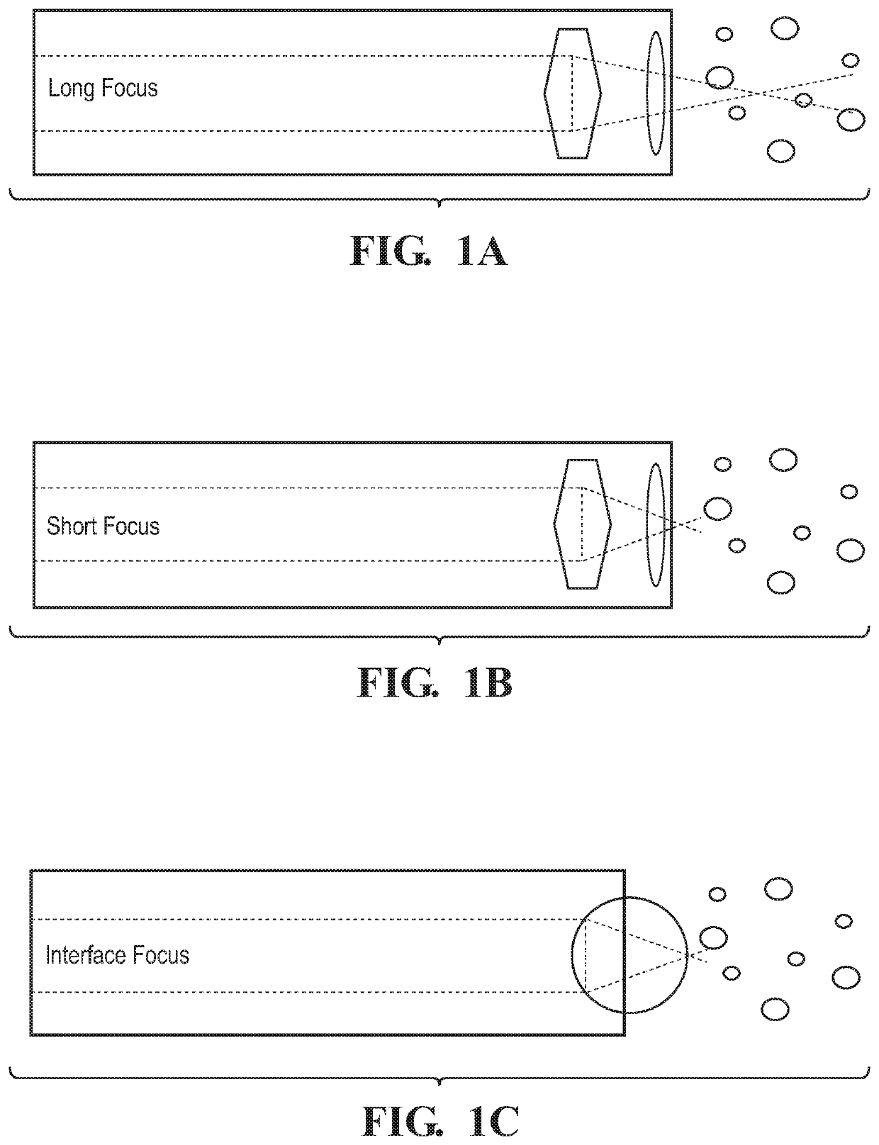
[0019]In broad and general terms, the immersion Raman probes disclosed herein use collimated light as opposed to a diverging fiber bundle or lens-based focusing geometry to deliver and collect light to and from a sample. This approach eliminates problems associated with chromatic aberrations generated using a single lens design. Chromatic aberrations generated by a single lens create a different focal point for different wavelengths within the sample. The laser wavelength is collected at its focal point, while longer Raman wavelengths collected at this focal point will experience divergence when leaving the same lens operating as the collection lens. Raman scattered light collected at its own focal point will be lower in intensity but will be collimated as it leaves the collection lens. To avoid chromatic blur within the sample it is important to have the same focal point for the laser and the complete range of Raman wavelengths effectively keeping the collection efficiency and path...


PUM

PropertyMeasurementUnit
output powersaaaaaaaaaa
Raman immersion probeaaaaaaaaaa
volumeaaaaaaaaaa

Abstract

Immersion Raman probes use collimated light as opposed to a diverging fiber bundle or lens-based focusing geometry to deliver and collect light to and from a sample, thereby eliminating problems associated with chromatic aberration. The probes convey counter-propagating excitation and collection beams to and from a distally sealed, signal-transmissive optical component such as a window immersed, in contact with, or otherwise exposed to a sample volume. The counter-propagating excitation and collection beams pass directly through the sealed optical component and into the sample volume in collimated form for Raman analysis thereof. The probe may further include a baffled sample chamber coupled to the distal end of the probe optic body, with one or more optical elements to reflect the counter-propagating beams. The sample chamber may be fixed or axially movable to facilitate path length adjustment. The invention finds utility in process Raman, microscopy and other applications.

Description

REFERENCE TO RELATED APPLICATIONS[0001]This application claims priority to, and the benefit of, U.S. Provisional Patent Application Ser. No. 62 / 744,839, filed Oct. 12, 2018, the entire content of which is incorporated herein by reference.FIELD OF THE INVENTION[0002]This invention relates generally to Raman spectroscopy and, in particular, to Raman immersion probes that can be used to analyze a full range of sample types including gases, liquids, slurries and solids.BACKGROUND OF THE INVENTION[0003]Most existing, commercially available Raman probes are based on a lens-based focused geometry that require selecting the correct focal length for the type of sample undergoing evaluation. As shown in FIG. 1A, clear liquids allow for long focal lengths within a sample, though particulates and bubbles may reduce throughput and degrade signal to noise. One solution, illustrated in FIG. 1B, involves optically moving the focal point and depth of field closer to the distal end of the probe. Desp...

Claims


Application Information

Patent Timeline
Patent Type & Authority Applications(United States)
IPC IPC(8): G01N21/65
CPCG01N2201/06113G01N2201/0846G01N21/65G01N2021/8521
Inventor OWEN, HARRY
Owner OWEN HARRY
Why Eureka
Try Eureka