Exposure apparatus and exposure method

Active Publication Date: 2020-04-23
TOPPAN PRINTING CO LTD
View PDF3 Cites 0 Cited by
  • Summary
  • Abstract
  • Description
  • Claims
  • Application Information

AI Technical Summary

Benefits of technology

The invention provides an exposure apparatus and method that reduces uneven exposure caused by the joining of exposure regions when multiple projection optical systems are used in a staggered arrangement.

Problems solved by technology

However, in the conventional scanning exposure apparatuses as described above, manufacturing errors occur between a pattern on a mask and an exposure pattern on a plate due to various factors.
In this case, there is a possibility of occurrence of unevenness of gradations of color in the lattice pattern which can be easily visually recognized.
For example, such unevenness is likely to be visually recognized particularly in a black matrix pattern or the like of a color filter used in liquid crystal apparatuses.
This is a problem that is unique to a scanning exposure apparatus using a plurality of projection optical systems.

Method used


Image

  • Exposure apparatus and exposure method
  • Exposure apparatus and exposure method
  • Exposure apparatus and exposure method

Examples


first embodiment

[0082]An exposure apparatus according to a first embodiment of the present invention will be described.

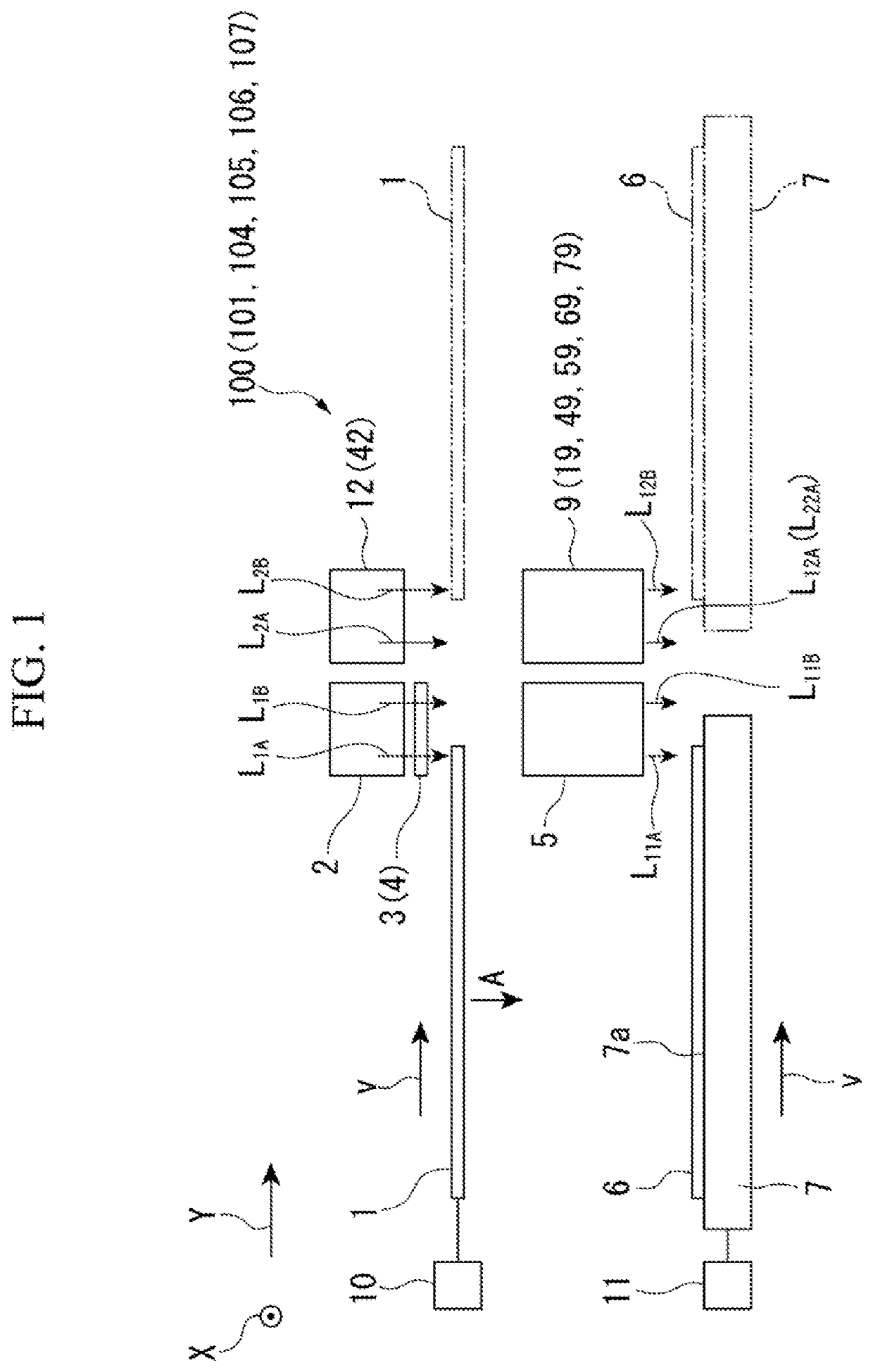
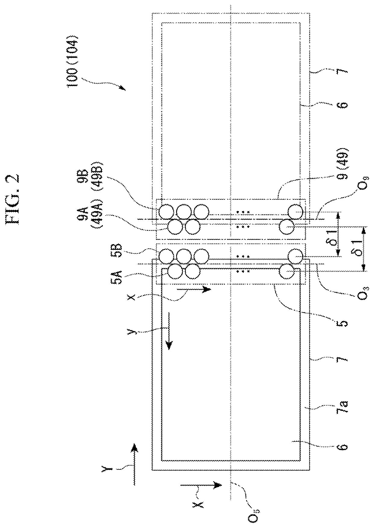
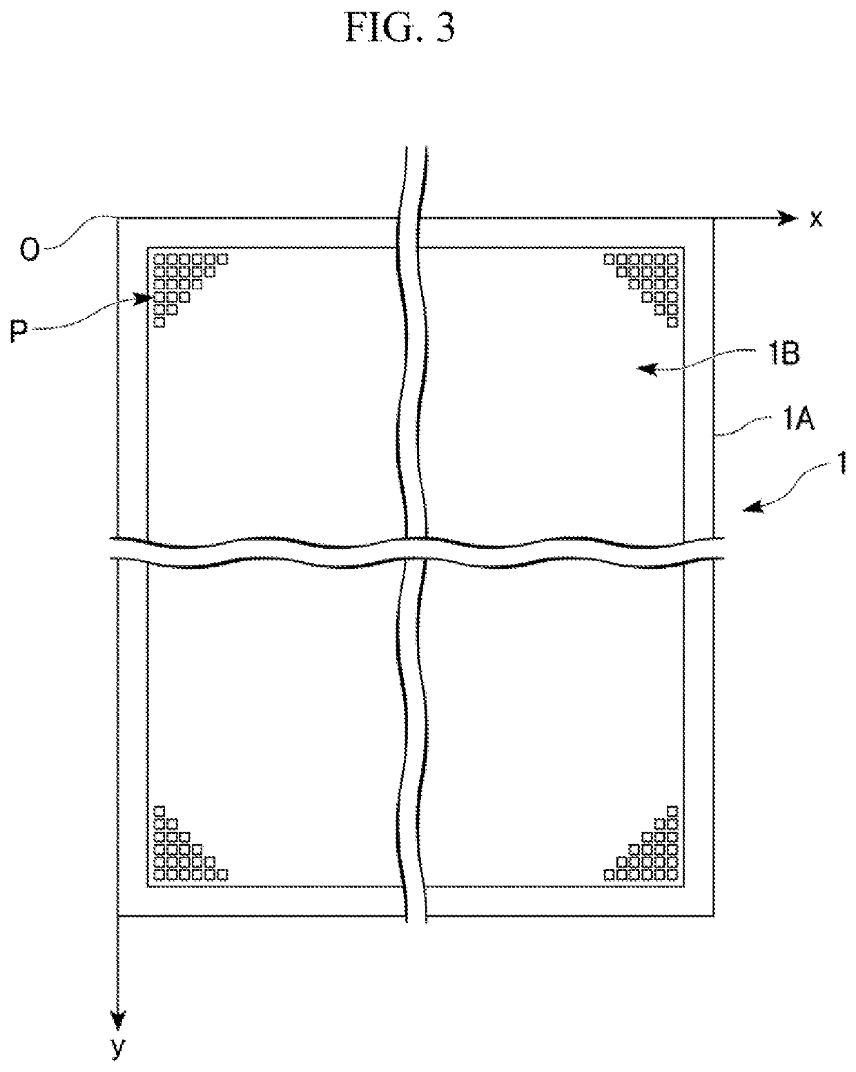
[0083]FIG. 1 is a schematic front view showing an example of the exposure apparatus of the first embodiment of the present invention. FIG. 2 is a plan view viewed in a direction of an arrow A in FIG. 1. FIG. 3 is a schematic plan view showing an example of an exposure photomask used in the exposure apparatus of the first embodiment of the present invention. FIG. 4 is an enlarged schematic view showing an example of a mask pattern of the exposure photomask used in the exposure apparatus of the first embodiment of the present invention. FIGS. 5A and 5B are schematic plan views showing examples of a field diaphragm used in the exposure apparatus of the first embodiment of the present invention.

[0084]An exposure apparatus 100 shown in FIGS. 1 and 2 is a scanning exposure apparatus performing an equal-magnification scanning exposure on an exposure subject 6 (exposure target) with an exp...

second embodiment

[0221]An exposure apparatus according to a second embodiment of the present invention will be described.

[0222]FIG. 14A is a schematic plan view showing an example of a main portion of the exposure apparatus of the second embodiment of the present invention. FIG. 14B is a cross-sectional view taken along D-D in FIG. 14A. FIG. 15 is a schematic plan view showing an example of the light transmission amount restrictor used in the exposure apparatus of the second embodiment of the present invention. FIG. 16 is a schematic graph showing a transmittance distribution along line E-E in FIG. 15. In FIG. 16, the horizontal axis indicates the position along line E-E, and the vertical axis indicates the transmittance.

[0223]As shown in FIG. 1, in place of the additional exposure illumination light source 12 and the additional exposure projection optical unit 9 of the exposure apparatus 100 of the first embodiment, an exposure apparatus 101 of the present embodiment includes an additional exposure...

third embodiment

[0245]An exposure apparatus according to a third embodiment of the present invention will be described.

[0246]FIG. 17A is a schematic front view showing an example of the exposure apparatus of the third embodiment of the present invention. FIG. 17B is a plan view viewed in a direction of an arrow F in FIG. 17A.

[0247]As shown in FIG. 17A, in place of the additional exposure illumination light source 12 and the additional exposure projection optical unit 9 of the exposure apparatus 100 of the first embodiment, an exposure apparatus 102 of the present embodiment includes an additional exposure illumination light source 52 (second light source) and an additional exposure projection optical unit 29 (correction stepper).

[0248]Hereinafter, points different from the first embodiment will be described mainly.

[0249]The additional exposure illumination light source 52 includes a first light source 52A performing irradiation of the second exposure light L2A similar to that of the first embodimen...


PUM


Abstract

An exposure apparatus includes: a first light source that generates first exposure light, a diaphragm having plurality of openings positioned between the first light source and an exposure photomask, a plurality of first projection optical systems that individually project an optical image realized by the first exposure light transmitted through each of the plurality of openings on an exposure target, a second light source that generates second exposure light, and a correction stepper. The correction stepper irradiates a light amount correction region with the second exposure light so as to limit an irradiation range of the exposure target to be irradiated with the second exposure light transmitted through the exposure photomask, and the light amount correction region is a region extending in a first direction by a width of a multi-opening region in a second direction in a plan view.

Description

CROSS REFERENCE TO RELATED APPLICATIONS[0001]This application is a continuation application based on a PCT Patent Application No. PCT / JP2018 / 026490, filed Jul. 13, 2018, whose priority is claimed on Japanese Patent Application No. 2017-143443 filed on Jul. 25, 2017, and Japanese Patent Application No. 2017-143490 filed on Jul. 25, 2017, the contents of which are hereby incorporated by reference in their entirety.BACKGROUND OF THE INVENTIONField of the Invention[0002]The present invention relates to an exposure apparatus and an exposure method.Description of the Related Art[0003]For example, scanning exposure apparatuses are known as apparatuses forming a pattern on a large-sized substrate used in liquid crystal apparatuses and the like.[0004]Examples of such a scanning exposure apparatus include an exposure apparatus disclosed in Japanese Unexamined Patent Application, First Publication No. H11-160887 (hereinbelow, referred to as Patent Document 1).[0005]In the exposure apparatus di...

Claims


Application Information

Patent Timeline
IPC IPC(8): G03F7/20
CPCG03F7/7015G02B19/00G03F7/20G03F7/7005G03F7/70275G03F7/70358G03F7/70625G03F7/70475G03F7/70308G03F7/70008G03F7/7025
Inventor OKUMURA, AKIHITOMOTODA, YOSHINORIMIYAJI, HIROAKI
Owner TOPPAN PRINTING CO LTD
Why Eureka
Try Eureka