Support Structure, Method and Lithographic Apparatus

a technology of supporting structure and lithographic apparatus, applied in the direction of microlithography exposure apparatus, mountings, instruments, etc., can solve the problems of negative influence of line of sight, negative result of lithographic process accuracy, deformation of sensor frame, etc., to prevent or reduce the transfer of deformations

Active Publication Date: 2020-04-23
ASML NETHERLANDS BV
View PDF4 Cites 5 Cited by
  • Summary
  • Abstract
  • Description
  • Claims
  • Application Information

AI Technical Summary

Benefits of technology

[0011]It is an object of the invention to provide a support structure, in particular a support structure for a sensor frame of a projection system of a lithogra

Problems solved by technology

Transferring vibrations would negatively influence the line of sight, i.e. the measurement direction, of the one or more sensors, and therewith would have negative result on the accuracy of the lithographic process, for example the overlay or focus obtained during the lithographic process.
Since a small deformation in the sensor frame may have a large eff

Method used


Image

  • Support Structure, Method and Lithographic Apparatus
  • Support Structure, Method and Lithographic Apparatus
  • Support Structure, Method and Lithographic Apparatus

Examples


Embodiment Construction

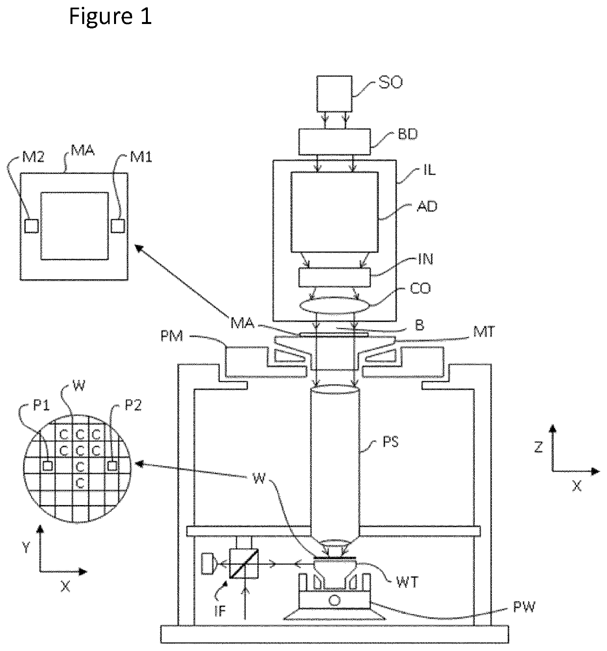
[0039]FIG. 1 schematically depicts a lithographic apparatus according to one embodiment of the invention. The apparatus comprises an illumination system IL, a support structure MT, a substrate table WT and a projection system PS.

[0040]The illumination system IL is configured to condition a radiation beam B. The support structure MT (e.g. a mask table) is constructed to support a patterning device MA (e.g. a mask) and connected to a first positioner PM configured to accurately position the patterning device in accordance with certain parameters. The substrate table WT (e.g. a wafer table) is constructed to hold a substrate W (e.g. a resist-coated wafer) W and connected to a second positioner PW configured to accurately position the substrate in accordance with certain parameters. The projection system PS is configured to project a pattern imparted to the radiation beam B by patterning device MA onto a target portion C (e.g. comprising one or more dies) of the substrate W.

[0041]The il...


PUM


Abstract

The invention relates to support structure, comprising: a first body; a second body; a first support having a first stiffness; a second support having a second stiffness, wherein the second body supports the first body at a first location via the first support, wherein the second body supports the first body at a second location via the second support; a position measurement system arranged to generate a deformation signal representative of a difference of deformation of the first body and the second body relative to each other; a first actuator to apply a force between the first body and the second body at or near the first location; a second actuator to apply a force between the first body and the second and body at or near the second location; wherein the support structure comprises a controller arranged to determine a deformation compensation signal on the basis of the first stiffness, the second stiffness and the deformation signal and to drive at least one of the first actuator and the second actuator on the basis of the deformation compensation signal to prevent or at least reduce deformation of the first body.

Description

CROSS-REFERENCE TO RELATED APPLICATIONS[0001]This application claims priority of EP application 17167347.8 which was filed on 20 Apr. 2017 and which is incorporated herein in its entirety by reference.FIELD OF THE INVENTION[0002]The present invention relates to a support structure arranged to support a first body by a second body. The invention further relates to a method to prevent or at least decrease the transfer of deformation from a second body to a first body supported by the second body, and a lithographic apparatus comprising the support structure.BACKGROUND ART[0003]A lithographic apparatus is a machine that applies a desired pattern onto a substrate, usually onto a target portion of the substrate. A lithographic apparatus can be used, for example, in the manufacture of integrated circuits (ICs). In that instance, a patterning device, which is alternatively referred to as a mask or a reticle, may be used to generate a circuit pattern to be formed on an individual layer of t...

Claims


Application Information

Patent Timeline
IPC IPC(8): G03F7/20
CPCG03F7/709G02B7/1827G03F7/70825G03F7/70833
Inventor BUTLER, HANS
Owner ASML NETHERLANDS BV
Why Eureka
Try Eureka