Touch panel structure and flexible touch display device

a touch display device and flexible technology, applied in the field of touch technology, can solve the problems of poor bending resistance, poor light transmittance, and flexible touch panel, and achieve the effects of reducing the bending stress that the first connecting portion receives when the touch panel is bent, reducing contact resistance, and smooth conducting

Active Publication Date: 2020-04-30
WUHAN CHINA STAR OPTOELECTRONICS SEMICON DISPLAY TECH CO LTD
View PDF5 Cites 8 Cited by
  • Summary
  • Abstract
  • Description
  • Claims
  • Application Information

AI Technical Summary

Benefits of technology

[0021]The beneficial effects of the present disclosure are as follows: a touch panel structure and a flexible touch display device provided by the present disclosure include a plurality of first touch electrode chains and a plurality of second touch electrode chains insulated and disposed crosswise to the first touch electrode chains. Each of the first touch electrode chains includes a plurality of spaced first touch electrodes, and the adjacent two of the first touch electrodes are electrically connected through a first connecting portion, the first connecting portion includes at least two conductive bridges; the two adjacent second touch electrodes are electrically connected by a second connecting portion, and the first connecting portion is stacked on the second connecting portion and insulated from the second connecting portion. Since the first connecting portion includes at least ...

Problems solved by technology

Under the existing technical conditions, due to the characteristics of the touch wire material and the structure of the touch panel, there are still some problems in making a flexible touch panel.
In terms of material, if the material of the touch control wire is Indium Tin Oxide (ITO), although the light transmittance of ITO is good, the bending resistance is poor; if the material of the touch control wire is silver nanowire (AgNW), silver (Ag), silver alloy, etc., the bending resistance is improv...

Method used


Image

  • Touch panel structure and flexible touch display device
  • Touch panel structure and flexible touch display device
  • Touch panel structure and flexible touch display device

Examples


first embodiment

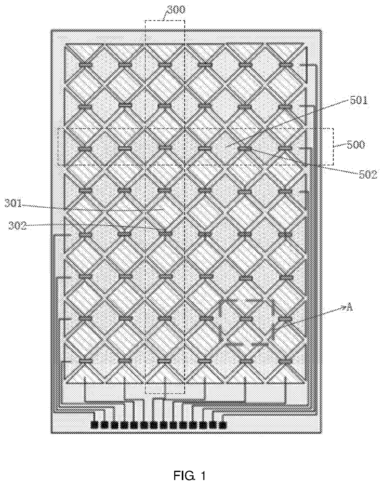
[0036]The present disclosure firstly provides a touch panel structure. Please also refer to FIG. 5 to FIG. 9, the touch panel structure of the present disclosure includes a substrate 1, a plurality of first touch electrode chains 3 disposed on the substrate 1, and a plurality of second touch electrode chains 5 disposed on the substrate 1.

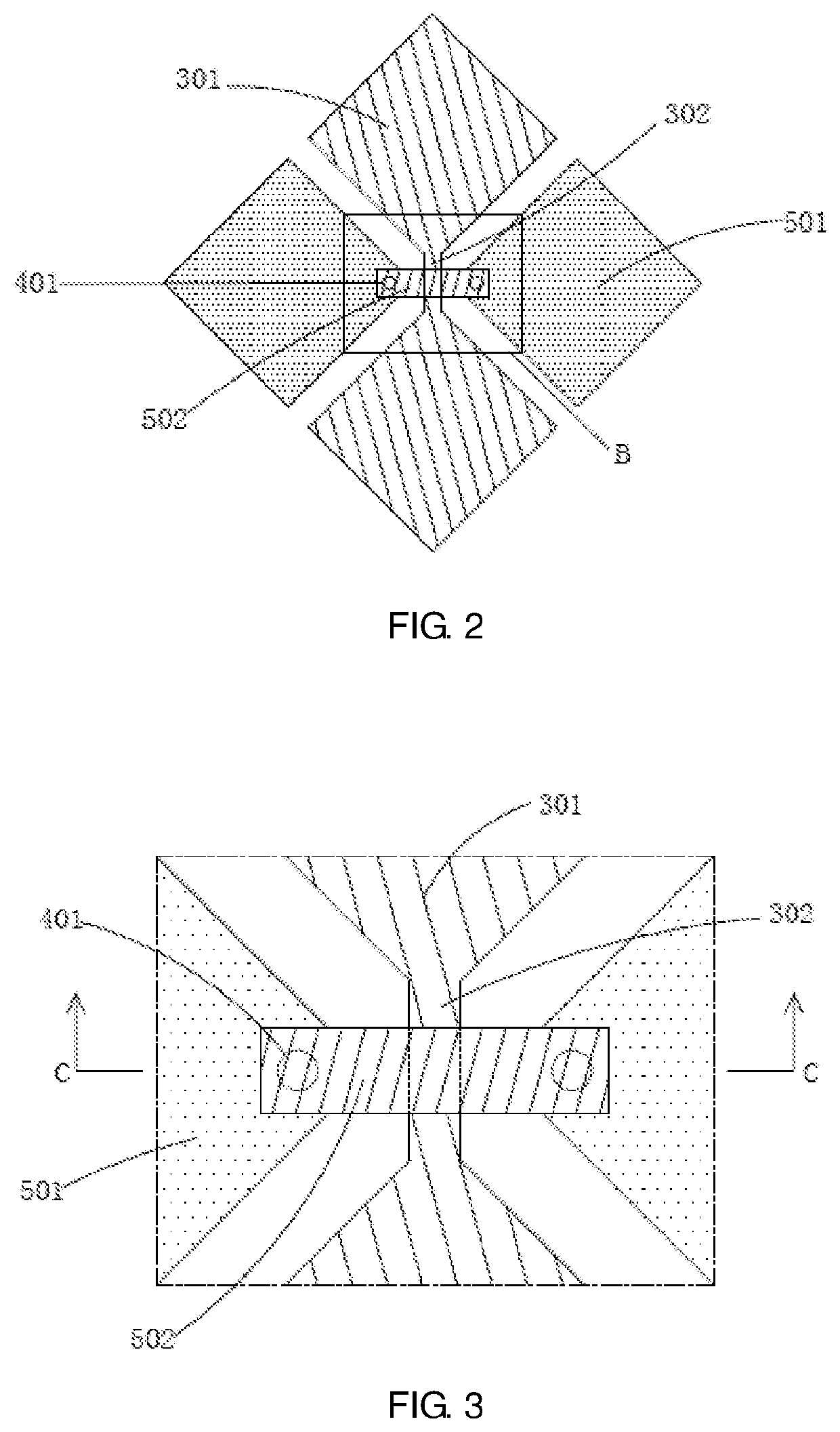
[0037]The plurality of the first touch electrode chains 3 are arranged at intervals, each of the first touch electrode chains 3 includes a plurality of spaced-apart first touch electrodes 31, and the adjacent two of the first touch electrodes 31 are electrically connected by a first connecting portion 33. In the first embodiment, the first connecting portion 33 includes two conductive bridges 331.

[0038]The plurality of the second touch electrode chains 5 are arranged at intervals, the second touch electrode chains 5 are arranged across and insulated from the first touch electrode chains 3; each of the second touch electrode chains 5 includes a plura...

third embodiment

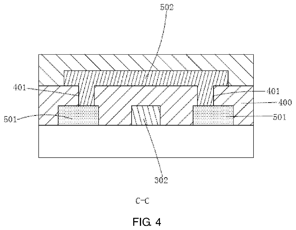
[0053]Since the first connecting portion 33 in the third embodiment includes two conductive bridges 331, the two ends of each of the conductive bridges 331 respectively contact the two adjacent first touch electrodes 31 so as to increase the contact area between the first connection portions 33 and the corresponding touch electrodes and reduce the contact resistance, so that the first connecting portion 33 and the corresponding touch electrode conduction smoothly. Due to the hollow between the different conductive bridges 331, a plurality of middle openings H are provided on each of the conductive bridges 331 and each of the via holes V on the same side of the first connecting portion 33 is not on the same straight line parallel to the second touch electrode chain 5, the bending stress that the first connecting portion 33 receives when the touch panel is bent can be greatly reduced, so as to reduce the risk of fracture of the connecting wire caused by the bending stress. In addition...

fourth embodiment

[0055]Since the first connecting portion 33 in the fourth embodiment includes three conductive bridges 331, the two ends of each of the conductive bridges 331 respectively contact the two adjacent first touch electrodes 31 so as to increase the contact area between the first connection portions 33 and the corresponding touch electrodes and reduce the contact resistance, so that the first connecting portion 33 and the corresponding touch electrode conduction smoothly. Due to the hollow between the different conductive bridges 331, a plurality of middle openings H are provided on each of the conductive bridges 331 and each of the via holes V on the same side of the first connection portion 33 is not on the same straight line parallel to the second touch electrode chain 5, the bending stress that the first connecting portion 33 receives when the touch panel is bent can be greatly reduced, so as to reduce the risk of fracture of the connecting wire caused by the bending stress. In addit...


PUM


Abstract

The present disclosure provides a touch panel structure and a flexible touch display device. The touch panel structure includes a plurality of first touch electrode chains and a plurality of second touch electrode chains insulated from and in cross-connection with the first touch electrode chains; each of the first touch electrode chains includes a plurality of spaced-apart first touch electrodes, and the adjacent two of the first touch electrodes are electrically connected through the first connecting portion, the first connecting portion includes at least two conductive bridges; two adjacent second touch electrodes are electrically connected through a second connecting portion, and the first connecting portion is stacked on the second connecting portion and insulated from the second connecting portion. The touch panel structure can not only increase the contact area between the first connection portion and the corresponding touch electrode but also reduce the contact resistance.

Description

RELATED APPLICATIONS[0001]The present application is a National Phase of International Application Number PCT / CN2018 / 076325, filed on Feb. 11, 2018, and claims the priority of China Application No. 201810073931.2, filed on Jan. 25, 2018.FIELD OF THE DISCLOSURE[0002]The present disclosure relates to a touch technology field, and more particularly to a touch panel structure and a flexible touch display device.BACKGROUND OF THE DISCLOSURE[0003]Flexible touch display is a very competitive display technology in the future. One of the great advantages of the flexible touch display device is that it can be bent so that a larger display area can be obtained while occupying less space and being easily portable and applicable. The conventional flexible touch display device generally adopts a flexible substrate, and sequentially fabricates elements such as a thin film transistor and an organic light-emitting diode on a flexible substrate, and finally adds a polarizer, a flexible touch panel an...

Claims


Application Information

Patent Timeline
IPC IPC(8): G06F3/044G06F3/041
CPCG06F3/0443G06F2203/04102G06F3/0412G06F3/0446G06F2203/04111G06F3/041G06F2203/04103
Inventor LIU, MINLUNDAI, QIBINGLIN, DAN
Owner WUHAN CHINA STAR OPTOELECTRONICS SEMICON DISPLAY TECH CO LTD
Why Eureka
Try Eureka