

Systems and Methods for Valve Sealing
a valve system and valve sealing technology, applied in the field of valve sealing systems, can solve the problems of extreme heat variance, expansion of various elements within the valve system, and dramatic heat variance of elements, so as to prevent product leakage and prevent steam loss
- Summary
- Abstract
- Description
- Claims
- Application Information
AI Technical Summary
Benefits of technology
Problems solved by technology
Method used
Image

Examples
Embodiment Construction
[0017]A description of embodiments of the present invention will now be given. It is expected that the present invention may take many other forms and shapes, hence the following disclosure is intended to be illustrative and not limiting, and the scope of the invention should be determined by reference to the appended claims and their equivalents.
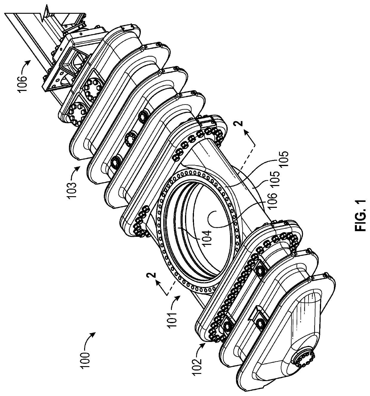
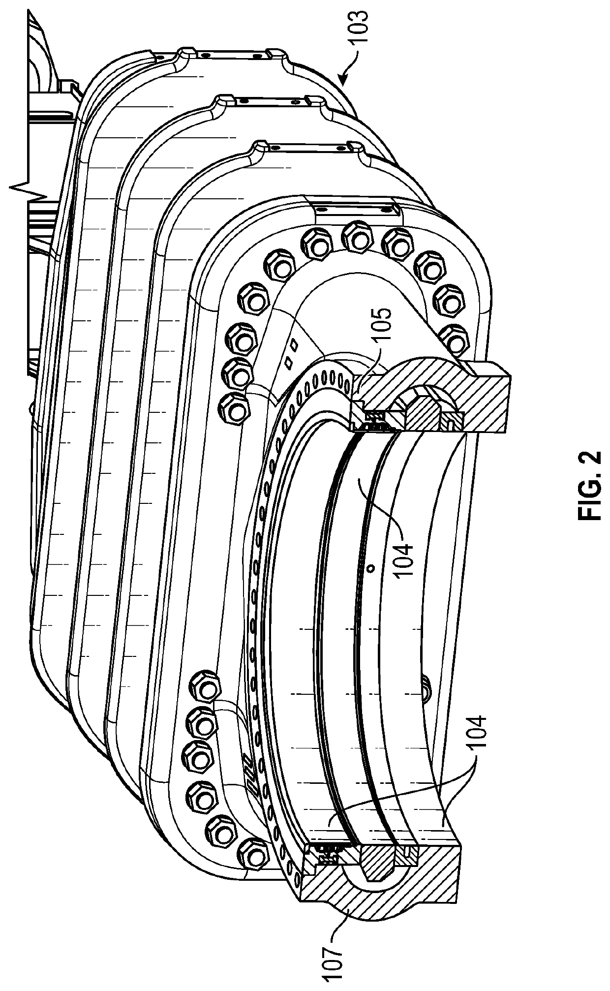
[0018]Embodiments of the present invention may be utilized in several types of valves used in the petroleum refining industry. One exemplary type of valve is illustrated in FIG. 1. This is an exemplary unheading valve 100 typically used in a decoking process. This exemplary valve 100 comprises a main body 101 that is typically detachably affixed to an upper bonnet 103. Upper bonnet 103 provides a gas-tight or pressurizable compartment for receiving at least a portion of a blind 104 during operation. A lower bonnet 102 may also be detachably affixed to main body 101 and may also provide a gas-tight, pressurizable compartment for receiving at...
PUM
| Property | Measurement | Unit |
|---|---|---|
| temperature | aaaaa | aaaaa |
| temperatures | aaaaa | aaaaa |
| length | aaaaa | aaaaa |
Abstract
Description
Claims
Application Information