Nonwoven web and method of making same

Active Publication Date: 2020-05-21
REIFENHAUSER GMBH & CO
View PDF4 Cites 0 Cited by
  • Summary
  • Abstract
  • Description
  • Claims
  • Application Information

AI Technical Summary

Benefits of technology

[0005]It is therefore an object of the present invention to

Problems solved by technology

As a rule, these effects lead to disadvantageous changes in the properties of the nonwoven web

Method used


Image

  • Nonwoven web and method of making same

Examples


Embodiment Construction

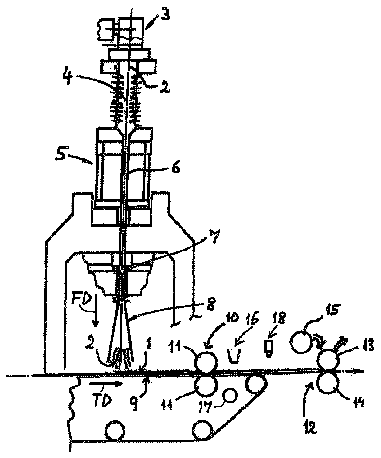
[0039]An apparatus for making a spun-consolidated nonwoven web 1 from continuous filaments 2, preferably of a thermoplastic synthetic resin, has a spinning device or spinneret 3 and, downstream therefrom in a filament-travel direction FD, a cooler 4. A stretcher 5 for stretching the filaments 2 follows the cooler 4 in the filament-flow direction FD. Preferably, this stretcher 5 has an intermediate passage 6 that converges in the direction of flow FD of the filaments 2, as well as an adjoining stretching passage 7. Recommendably, the assembly of the cooler 4 and the stretcher 5 is a closed system. Apart from the supply of cooling air or process air in the cooler 4, no further air supply is provided in this closed system. According to a preferred embodiment, a diffuser 8 is downstream of the stretcher 5 in the direction of flow FD of the filaments 2. Advantageously, the filaments 2 are deposited downstream of the diffuser 8 on a screen deposition belt 9 to form the nonwoven web 1. Pre...


PUM

PropertyMeasurementUnit
Temperatureaaaaaaaaaa
Timeaaaaaaaaaa
Pressureaaaaaaaaaa

Abstract

A nonwoven web is made by first depositing fibers as a nonwoven web in a deposition area, then conveying the web away from the deposition area in a web-travel direction, preconsolidating the web in the path, and passing the preconsolidated web between a pair of rollers that compress and final consolidate the preconsolidated web. One of the rollers is separated from the web such that final consolidation of the web at a starting level is stopped and at the same time or immediately beforehand upstream preconsolidation of the web increased. After separating the one roller from the web, another roller is engaged with the web at the consolidation station and then final consolidation is recommenced, whereupon upstream preconsolidation of the web is reduced back to the starting level.

Description

FIELD OF THE INVENTION[0001]The present invention relates to a nonwoven. More particularly this invention concerns a method of and apparatus for making a nonwoven from fibers.BACKGROUND OF THE INVENTION[0002]A nonwoven web from fibers, particularly from plastic fibers, is typically made by spinning the fibers, then cooling them, and depositing them as a mat or nonwoven web in a deposition area, particularly on a deposition or screen belt. Then the mat passes through a preconsolidater then through a first calender-roller assembly. At the downstream end of the production line the thus preconsolidated and calendered nonwoven web is wound up, or otherwise processes for further use.[0003]A method and apparatus of the above-described type are known from practice in various embodiments. When calendering the nonwoven web with a calender roller, the need can arise during operation to replace the calender roller. Such a case arises, for example, when the properties of the calender roller are ...

Claims


Application Information

Patent Timeline
IPC IPC(8): D04H1/44D04H1/724D04H1/64D04H1/559
CPCD04H1/64D04H1/724D04H1/44D04H1/559D04H3/10D04H3/08D04H17/10D04H3/005D04H3/12D04H3/16D01D5/088D01D5/16D04H3/14D04H1/488D04H1/593D04H17/12D21G1/00D01D5/08D01D5/0985D01H3/00D01H3/16
Inventor FREY, DETLEFGEUS, HANS-GEORGMAAS, MICHAELNEUENHOFER, MARTINNITSCHKE, MICHAELNOACK, CHRISTINEKOPP, HARTMUT
Owner REIFENHAUSER GMBH & CO
Why Eureka
Try Eureka