
System and method for the automated production of a cable set

a technology of cable sets and automatic production, which is applied in the direction of cable/conductor manufacturing, cable installation apparatus, contact member assembly/disassembly, etc., can solve the problems of high manual work, high production and handling costs of such cable sets, and the production of cable sets especially for the automotive industry continues to require a large amount of manual work, etc., to achieve convenient custom configuration and efficient design

Active Publication Date: 2020-05-21
LEONI BORDNETZ SYST
View PDF0 Cites 5 Cited by
  • Summary
  • Abstract
  • Description
  • Claims
  • Application Information

AI Technical Summary

Benefits of technology

The patent describes a scaffolding system for processing cable sets in a cable assembly plant. The scaffolding system is designed to allow for efficient transport of individual line elements between processing stations. The system includes two tracks, one for each processing station, which are mechanically interconnected. This allows for easy customization and flexibility in the configuration of the plant. The second track system includes movable second transporters that can be distributed to different distribution structures in two dimensions, making it more efficient for processing. Additionally, each processing station has a separate manipulator for high clock rates of independent processing within the station. Overall, the system provides a flexible and efficient solution for cable assembly plants.

Problems solved by technology

The production and handling of such cable sets is expensive.
Due to the large variety of types and variations of these individual cable sets, automating the production of such cable sets is difficult, which is why until today the production of cable sets especially for the automotive industry continues to require a high amount of manual work.

Method used


Image

  • System and method for the automated production of a cable set
  • System and method for the automated production of a cable set
  • System and method for the automated production of a cable set

Examples


Embodiment Construction

[0072]In the figures, identically-acting parts are provided with the same reference numerals.

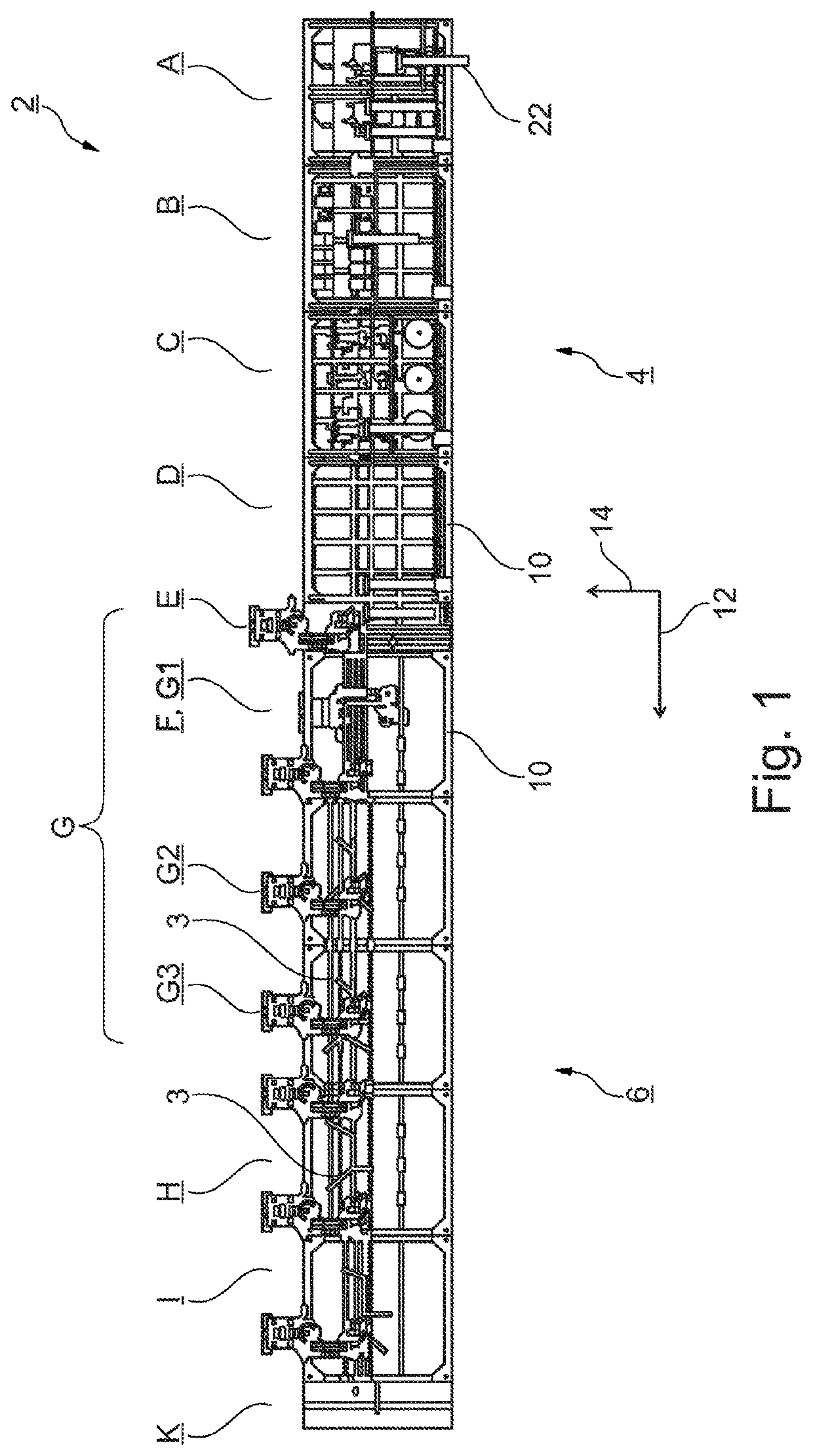
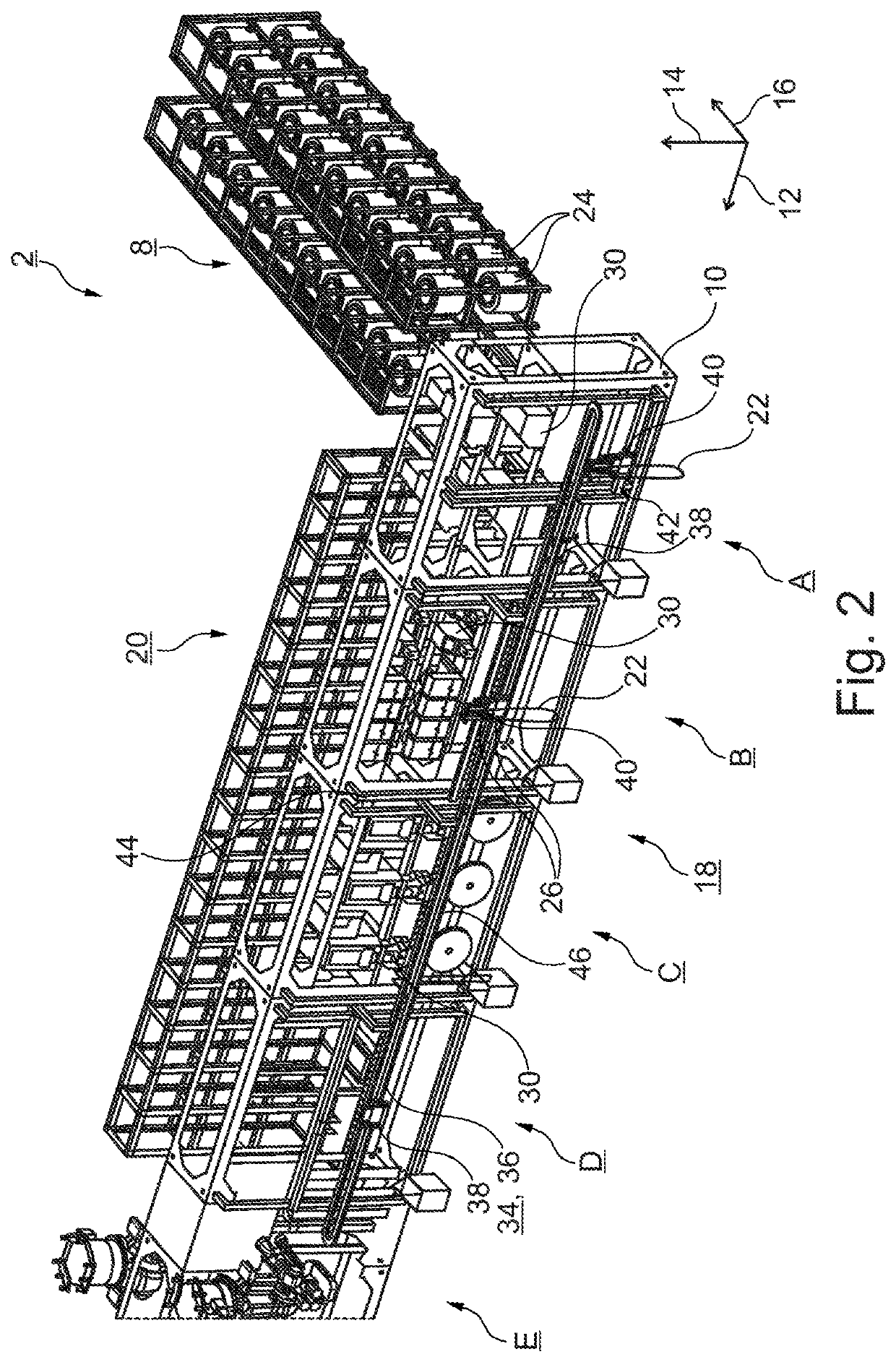
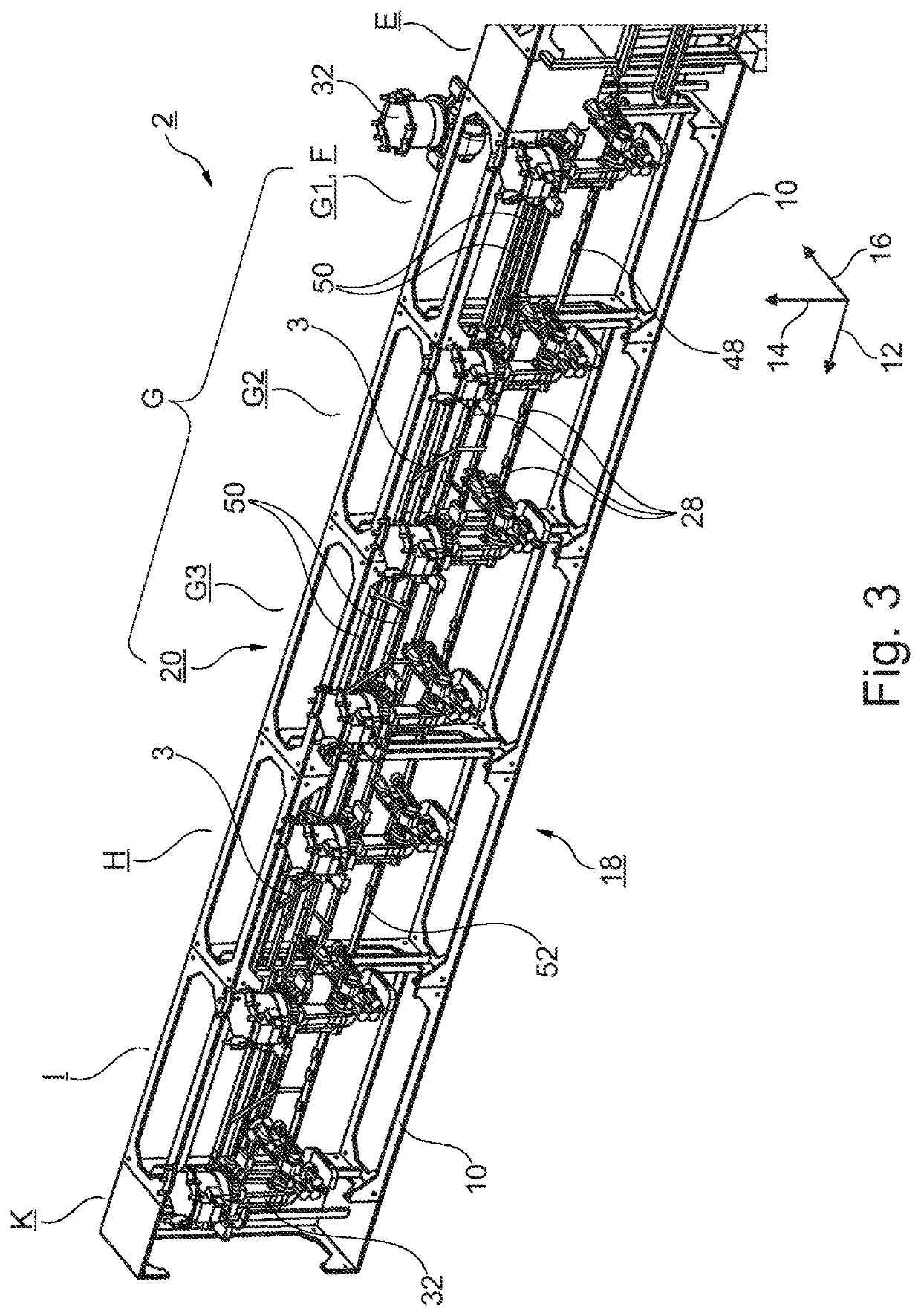
[0073]The system 2 shown in FIGS. 1 to 3 serves for the automated production of a cable set 3 and is set up modularly from a plurality of individual processing stations. The system has a first part 4 with first processing stations A, B, C, D and a second part with second processing stations E, F, G, H, I, K. Upstream of the first part 4, a warehouse 8 is also disposed, which is designed in the manner of a high-bay warehouse. The individual processing stations A to K each have a scaffolding 10, which essentially defines a scaffolding frame within which processing units for carrying out different work steps are arranged in the first part 4.

[0074]The scaffoldings 10 are attached directly adjacent to each other and form a particular linearly extending scaffolding arrangement. The scaffoldings 10 are lined up in a longitudinal direction 12 to each other. The scaffoldings 10 are set up in the mann...


PUM

PropertyMeasurementUnit
lengthaaaaaaaaaa
diameteraaaaaaaaaa
distribution structureaaaaaaaaaa

Abstract

A system for the automated production of a cable set, which has a branched structure of a plurality of individual line elements. In a modular set-up in the first part, a plurality of first processing stations, and in the second part, a plurality of second processing stations are arranged. In the first part, there is an automatic preparation of the individual line elements, which are then collected in a buffer station at the end of the first part. In the second part, the prepared individual line elements are assembled into the cable set. The line elements are plugged into connector casings in a connector station and transferred to second transporters, and via which the branched structure of the cable set is then formed by moving along second tracks. In this spread-out branched structure, a fixing of the line elements to one another takes place in a fixing station.

Description

[0001]This nonprovisional application is a National Stage of International Application No. PCT / EP2018 / 059016, which was filed on Apr. 9, 2018, and which claims priority to German Patent Application No. 10 2017 206 139.1, which was filed in Germany on Apr. 10, 2017 and which are both herein incorporated by reference.BACKGROUND OF THE INVENTIONField of the Invention[0002]The present invention relates to a system and a method for the automated production of a cable set, in particular for a motor vehicle.Description of the Background Art[0003]A cable set generally includes a plurality of individual line elements, which are connected to each other. The line elements are in particular insulated conductors, twisted conductors (pairs), optical waveguides or prefabricated sub-lines, such as sheathed cables. An insulated conductor is generally understood to be a conductor surrounded by insulation, either a conductor wire or a stranded conductor. A respective cable set has a branched structure...

Claims


Application Information

Patent Timeline
Patent Type & Authority Applications(United States)
IPC IPC(8): H01B13/012H01B7/00H01R43/20B25J11/00B60R16/02
CPCH01B13/01209H01B7/0045B25J11/005H01B13/01236H01R43/20B60R16/0207H01R43/28H02G1/1248B25J11/00
Inventor DIETLEIN, FABIANGUNI, CHRISTIANHEISLER, PAULJAECKLEIN, ROLANDMARTINS, PAULOTAVSEL, ONUR
Owner LEONI BORDNETZ SYST
Learn More