Ventilation unit, system and method

a technology for indoor air and ventilation units, applied in ventilation systems, lighting and heating apparatus, heating types, etc., can solve the problems of allowing outdoor air pollutants into the home, unable to replace the need for ventilation with outdoor air, and ventilation is an unobtrusive, robust and low-cost means to reduce indoor air pollution, etc., to achieve the effect of improving the controllability of a purely passive natural ventilation system, high airflow rate and increasing ventilation air flow ra

Active Publication Date: 2020-05-28
VERSUNI HLDG BV
View PDF0 Cites 10 Cited by
  • Summary
  • Abstract
  • Description
  • Claims
  • Application Information

AI Technical Summary

Benefits of technology

[0023]This ventilation unit relies on natural air flow caused by a naturally occurring pressure difference between the outside and inside space, for example dependent on the outside wind direction and speed. The unit avoids the need for bulky mechanical HVAC systems but improves the controllability of a purely passive natural ventilation system. Instead it involves the use of a unit which may be considered to be a “ventilation air cleaning device” (VACD). The unit may for example be mounted in walls or windows. The unit still relies on natural ventilation with incoming and exiting air flows that are driven by the air pressure differentials between outdoors and indoors that exist at the VACD locations. The VACD does not comprise a mechanical ventilator and is designed such that it can sustain a high airflow rate, even when the pressure differential across the VACD is relatively small.
[0024]The unit is therefore particularly suitable for use in well-insulated homes that would otherwise frequently suffer from inadequate ventilation levels. The unit is for example capable of cleaning the incoming ventilation air from particle pollution and can for example reduce the incoming ventilation air flow rate down to the minimum required ventilation level in case of extreme outdoor air temperatures and / or relative humidity (RH) levels.
[0025]In addition, the ventilation air flow rate can be increased to respond to a measured high indoor particle pollution level. The unit thus provides an energy-efficient and unobtrusive method that is capable of actively responding to changing indoor and outdoor conditions, thereby supplying indoor spaces with controlled amounts of a least partially-cleaned ventilation air from outdoors.

Problems solved by technology

The use of indoor air cleaners can help to improve the indoor air cleanliness but cannot replace the need for ventilation with outdoor air.
In addition, because the overall indoor air pollution level is usually higher than the outdoor air pollution level, ventilation is an unobtrusive, robust and low-cost means to lower the indoor air pollution level.
While natural ventilation is advantageous because of its unobtrusiveness, it has the disadvantage that it also allows outdoor air pollutants to enter the home.
This is particularly problematic in places that suffer from high outdoor air pollution levels.
Well-insulated low-leakage buildings are notorious for suffering from poor indoor air quality conditions because the pertaining natural ventilation levels are often too low.
Finally, natural ventilation can adversely affect indoor comfort conditions when the natural ventilation level is high in combination with extreme (cold, hot) outdoor air temperatures in winter and summer.
Fibrous particle filters cannot easily be regenerated and must be discarded as waste.
However, HVAC systems are costly, bulky, noisy, energy-hungry, and require ductwork for air transport throughout the building.
Similarly, fan operated electrostatic particle precipitation filters or mechanical fibrous particle filters also consume significant amounts of energy.
Reliance on natural ventilation is therefore often preferred in temperate climates but problematic for the indoor air quality in situations wherein a high outdoor air pollution exists.

Method used


Image

  • Ventilation unit, system and method
  • Ventilation unit, system and method
  • Ventilation unit, system and method

Examples


Embodiment Construction

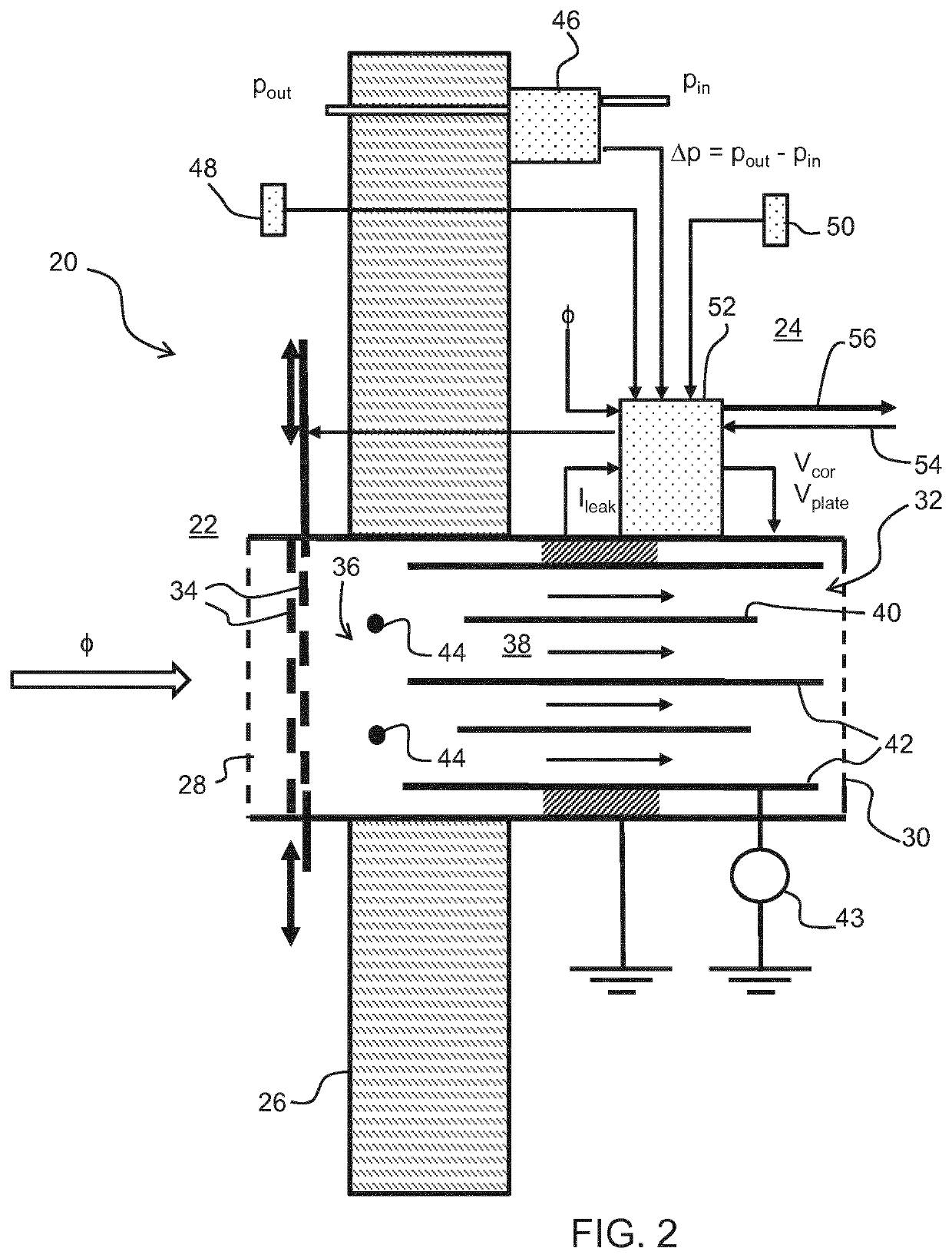
[0069]The invention provides a ventilation unit for ventilating an indoor space which incorporates an air cleaning device and a mechanical restrictor for controlling a restriction to a flow resulting from a pressure differential across the unit. There is determination of the inside and outside air pressures in the vicinity of the unit and of air quality parameters inside and outside. The air cleaning device and the mechanical restrictor are controlled in dependence on the determined local air pressures and air quality parameters. This provides a fan-less, and hence low-power ventilation unit, which relies on throttling the natural air flow across the unit to provide flow control, and hence enable control of air quality. The air cleaning device may be operated only when the flow is into the inside space, saving power.

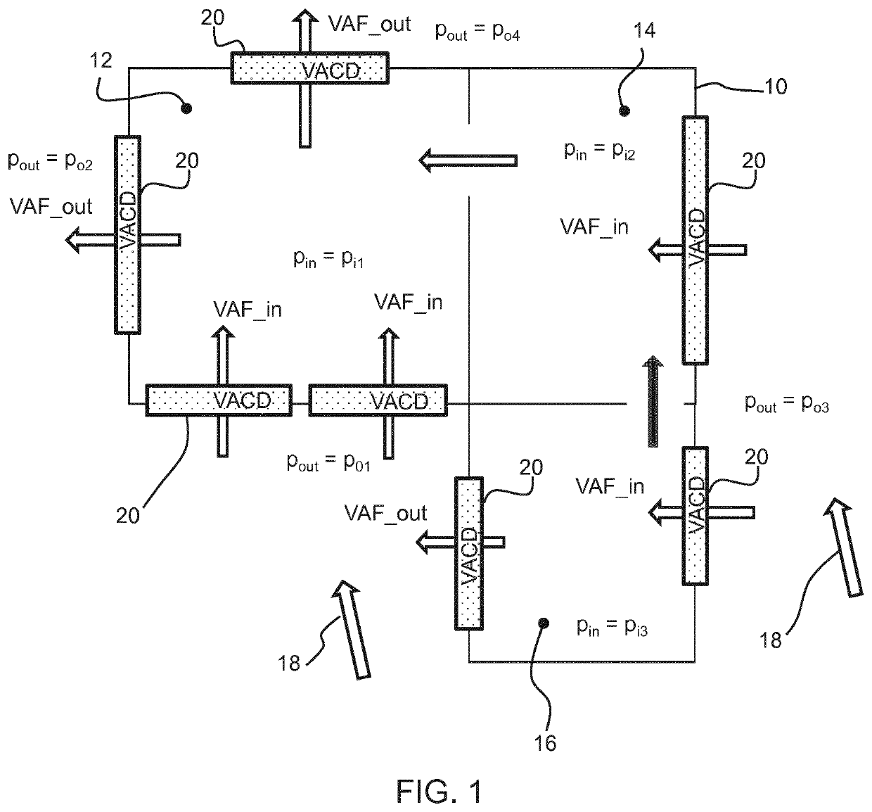
[0070]FIG. 1 shows a top view of a building 10 having three connected indoor spaces (i.e. rooms) 12, 14, 16. The building is located in an outdoor environment wherein a ...


PUM


Abstract

A ventilation unit is for ventilating an indoor space, and incorporates an air cleaning device and mechanical restrictor for controlling a restriction to a flow resulting from a pressure differential across the unit. There is determination of the inside and outside air pressures in the vicinity of the unit and of air quality parameters inside and outside. The air cleaning device and the mechanical restrictor are controlled in dependence on the determined air pressures and air quality parameters. This provides a fan-less, and hence low-power ventilation unit, which relies on throttling the natural air flow across the unit to provide flow control, and hence enable control of air quality. The air cleaning device may be operated only when the flow is into the inside space, saving power.

Description

FIELD OF THE INVENTION[0001]The invention relates to methods and apparatus for ventilating an indoor air space.BACKGROUND OF THE INVENTION[0002]A healthy indoor climate can be attained by providing comfortable relative humidity and temperature (RH,T) conditions and clean indoor air. The use of indoor air cleaners can help to improve the indoor air cleanliness but cannot replace the need for ventilation with outdoor air.[0003]Ventilation is effective for displacing a host of indoor-generated pollutants and odors that cannot (easily) be cleaned by means of filtration. Furthermore, it displaces indoor-generated moisture and CO2 to outdoors. In addition, because the overall indoor air pollution level is usually higher than the outdoor air pollution level, ventilation is an unobtrusive, robust and low-cost means to lower the indoor air pollution level.[0004]Most residential homes and many buildings / offices rely on natural ventilation, where outdoor air enters and indoor air leaves the “l...

Claims


Application Information

Patent Timeline
Patent Type & Authority Applications(United States)
IPC IPC(8): F24F11/74F24F13/02F24F13/12F24F7/04F24F7/003F24F11/00F24F110/10F24F110/12F24F110/20F24F110/22F24F110/40F24F110/52
CPCF24F2110/12F24F2110/22F24F2003/1682F24F2110/20F24F2110/40F24F2110/10F24F7/04F24F2011/0002F24F11/74F24F13/12F24F13/0227F24F2110/52F24F2007/004F24F2110/50F24F8/30Y02B30/70F24F7/003
Inventor MARRA, JOHANNESKOERBER, ACHIM GERHARD ROLFRONDA, CORNELIS REINDER
Owner VERSUNI HLDG BV
Why Eureka
Try Eureka