Thermal management system for electric vehicle

a technology for electric vehicles and management systems, applied in vehicle heating/cooling devices, electric generators, transportation and packaging, etc., can solve the problems of large space occupation and large number of parts required in the vehicle, and achieve the effect of increasing the indoor temperature of the vehicl

Active Publication Date: 2020-06-11
HYUNDAI MOTOR CO LTD +1
View PDF0 Cites 1 Cited by
  • Summary
  • Abstract
  • Description
  • Claims
  • Application Information

AI Technical Summary

Benefits of technology

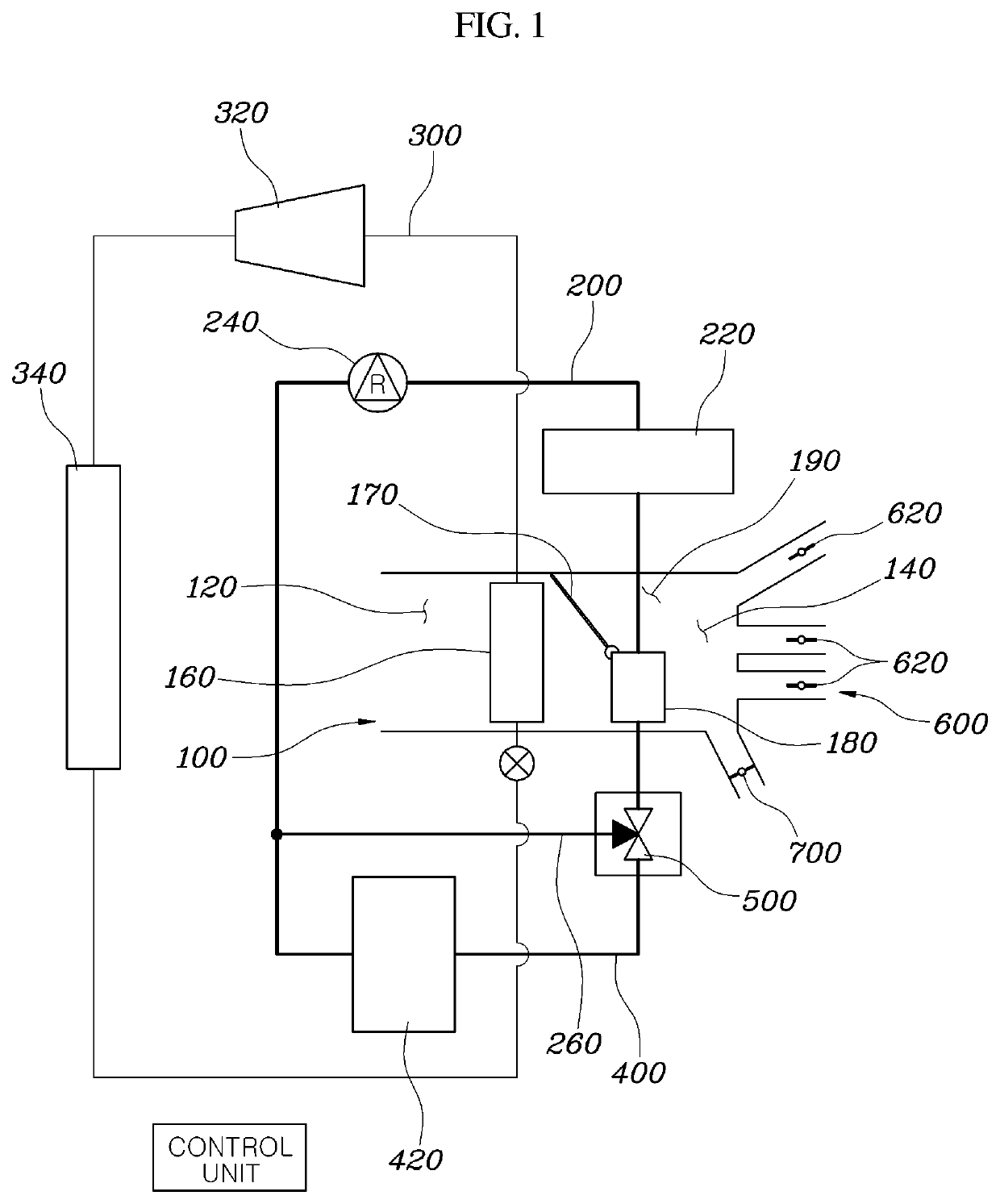
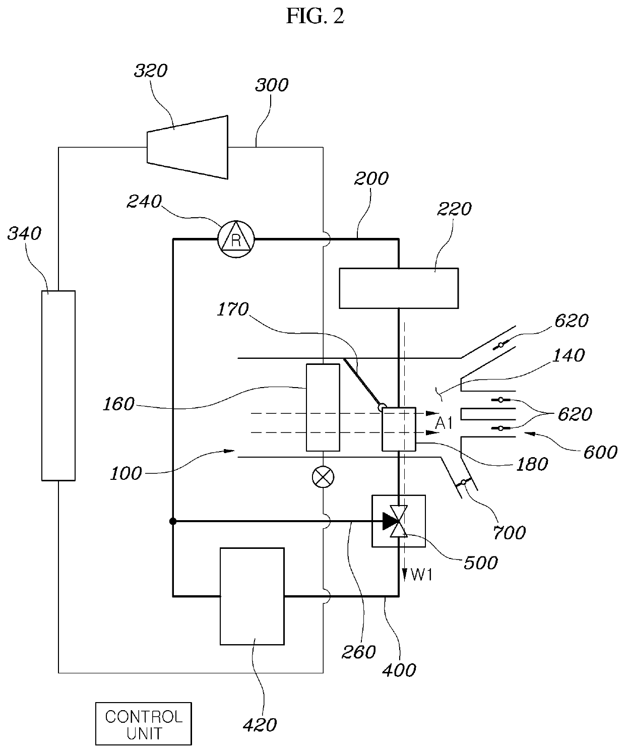
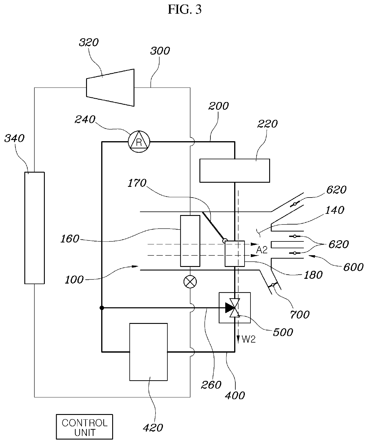
[0008]Further, inside air or outdoor air may be introduced into the air inlet unit of the inside air conditioning unit, and the air outlet unit may be connected to an indoor space of the vehicle. The control door may be disposed between the cooling core and the heating core to control whether air flowing through the cooling core flows into the heating core. The branch flow path may be branched at a downstream point of the heating core of the first flow path, pass through the high voltage battery heat exchange unit, and join again at an upstream point of the electric heater of the first flow path. The control valve may adjust a supply of the first refrigerant to the branch flow path.
[0009]Additionally, a flow space may be formed on a side of the heating core inside the inside air conditioning unit, and air may flow through the cooling core based on the operation of the control door, and then flow into the air outlet unit through the flow space or pass through the cooling core and then flow into the air outlet unit through the heating core. The thermal management system for the electric vehicle may further include a controller configured to operate the compressor, the electric heater, the control door and the control valve to adjust a temperature of an interior of the vehicle or a high voltage battery.
[0010]In a first mode for increasing the indoor temperature of the vehicle or the temperature of the high voltage battery, the controller may be configured to operate the electric heater, adjust the control valve to allow the first refrigerant to flow through the branch flow path, and adjust the control door to allow air to flow through the heating core. In a second mode for increasing the indoor temperature of the vehicle and cooling the high voltage battery, the controller may be configured to adjust the control valve to allow the first refrigerant to flow through the branch flow path, and adjust the control door to allow air to flow through the heating core.
[0011]In a third mode for cooling the interior of the vehicle and increasing the temperature of the high voltage battery, the controller may be configured to operate the compressor and the electric heater, adjust the control valve to allow the first refrigerant to flow through the first flow path and the branch flow path at the branch point, and adjust the control door to allow air to flow through the flow space. In a fourth mode for cooling the interior of the vehicle and the high voltage battery and dehumidifying outside air or inside air of the vehicle, the controller may be configured to operate the compressor, adjust the control valve to allow the first refrigerant to flow through the first flow path and the branch flow path at the branch point, and adjust the control door to allow air to flow through the electric heater.
[0012]In a fifth mode for maintaining the temperature of the high voltage battery and increasing the indoor temperature of the vehicle, the controller may be configured to operate the electric heater, adjust the control valve to allow the first refrigerant to flow through the first flow path, and adjust the control door to allow air to flow through the heating core. In a sixth mode for maintaining the indoor temperature of the vehicle and increasing the temperature of the high voltage battery, the controller may be configured to operate the electric heater, and adjust the control valve to allow the first refrigerant to flow through the branch flow path at the branch point. In a seventh mode for maintaining the temperature of the high voltage battery and cooling the interior of the vehicle, the controller may be configured to operate the compressor to control air to flow through the flow space.
[0013]Further, an outlet for discharging air to an outside of the vehicle may be formed in the air outlet unit of the inside air conditioning unit and an opening and closing door that adjusts the opening and closing of the outlet may be provided. In an eighth mode for maintaining the indoor temperature of the vehicle and cooling the high voltage battery, the controller may be configured to operate the compressor, adjust the control valve to allow the first refrigerant to flow through the branch flow path, adjust the control door to allow air to flow through the heating core, and adjust the outlet to allow the air to be discharged to the outside of the vehicle.

Problems solved by technology

However, unlike the existing vehicle, an electric vehicle operates by obtaining driving energy through electric energy from a battery module rather than the fossil fuel.
To provide such a separate thermal management system, a substantial number of parts are required and a large space is occupied within the vehicle.

Method used


Image

  • Thermal management system for electric vehicle
  • Thermal management system for electric vehicle
  • Thermal management system for electric vehicle

Examples


Embodiment Construction

[0024]It is understood that the term “vehicle” or “vehicular” or other similar term as used herein is inclusive of motor vehicles in general such as passenger automobiles including sports utility vehicles (SUV), buses, trucks, various commercial vehicles, watercraft including a variety of boats and ships, aircraft, and the like, and includes hybrid vehicles, electric vehicles, plug-in hybrid electric vehicles, hydrogen-powered vehicles and other alternative fuel vehicles (e.g. fuels derived from resources other than petroleum). As referred to herein, a hybrid vehicle is a vehicle that has two or more sources of power, for example both gasoline-powered and electric-powered vehicles.

[0025]Although exemplary embodiment is described as using a plurality of units to perform the exemplary process, it is understood that the exemplary processes may also be performed by one or plurality of modules. Additionally, it is understood that the term controller / control unit refers to a hardware devi...


PUM


Abstract

An electric vehicle thermal management system is provided. The system includes an inside AC unit having an air inlet unit and an air outlet unit and a cooling core embedded therein. A heating core is disposed between the air outlet unit of the inside AC unit and the cooling core and a control door is disposed inside the inside AC unit to adjust air supply to the heating core. A first flow path circulates to pass through the heating core and includes an electric heater. A branch flow path is branched from downstream point of the heating core of the first flow path and passing through a high voltage battery heat exchange unit. A control valve is disposed in a branch point between the first flow path and the branch flow path and a second flow path circulates between a compressor and a condenser and the cooling core.

Description

CROSS REFERENCE TO RELATED APPLICATION[0001]The present application claims priority to Korean Patent Application No. 10-2018-0158959, Dec. 11, 2018 the entire contents of which is incorporated herein for all purposes by this reference.BACKGROUND1. Technical Field[0002]The present disclosure relates to a thermal management system for an electric vehicle, and more particularly, to a thermal management system that increases or decreases a temperature of the interior of a vehicle or a high voltage battery within the electric vehicle.2. Description of the Related Art[0003]Traditionally, a vehicle has operated by obtaining driving energy from the combustion of a fossil fuel. However, unlike the existing vehicle, an electric vehicle operates by obtaining driving energy through electric energy from a battery module rather than the fossil fuel. The battery module includes a plurality of battery cells connected in series. To effectively charge and discharge the battery module, the battery mod...

Claims


Application Information

Patent Timeline
Patent Type & Authority Applications(United States)
IPC IPC(8): B60H1/00B60H1/22B60H1/24B60H1/32
CPCB60H2001/2253B60H1/00642B60H1/24B60H1/2225B60H1/2218B60H1/00392B60H1/00485B60H1/00278B60H1/00007B60H1/323H01M10/613H01M10/615H01M10/625B60H1/0005B60H1/00678Y02E60/10Y02T10/70B60H1/00321B60H1/00821B60H1/00878B60H1/3205B60H3/024
Inventor LEE, SANG SHINOH, MAN JUCHUNG, SO LAKIM, JAE WOONG
Owner HYUNDAI MOTOR CO LTD
Why Eureka
Try Eureka