Switching Power Supply Device

a power supply device and power supply technology, applied in the direction of power conversion systems, dc-dc conversion, instruments, etc., can solve the problems of increasing the consumption power and cost of controllers, reducing the control resolution, and increasing the clock frequency, so as to improve the effect of improving the resolution of pwm control and phase shift control

Active Publication Date: 2020-06-11
HITACHI ASTEMO LTD
View PDF0 Cites 1 Cited by
  • Summary
  • Abstract
  • Description
  • Claims
  • Application Information

AI Technical Summary

Benefits of technology

[0010]According to the present invention, a switching power supply device of a digital control system can use a high-performance digital processor, and improve resolutions of PWM control and phase shift control without providing an additional circuit and delaying a response. Consequently, it is possible to provide the switching power supply device which has a high voltage control resolution, is low cost, makes a response at a high speed and causes a little voltage ripple.

Problems solved by technology

This digital control system has a problem that a minimum change range of the operation amount is limited to a time corresponding to one cycle of the clock signal, and therefore a voltage control resolution lowers compared to the analog control system.
However, this method has a problem that the increase of the clock frequency increases consumption power and cost of a controller.

Method used


Image

  • Switching Power Supply Device
  • Switching Power Supply Device
  • Switching Power Supply Device

Examples


first embodiment

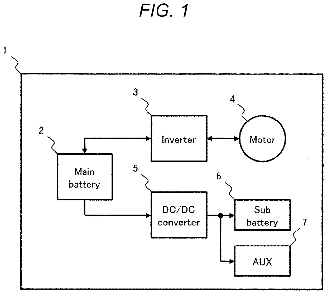
[0024]The first embodiment of the present invention will be described with reference to FIGS. 2 to 4. The present embodiment improves a voltage control resolution in a case where a non-insulation type buck converter of PWM (Pulse Width Modulation) control is used as a DC / DC converter 5.

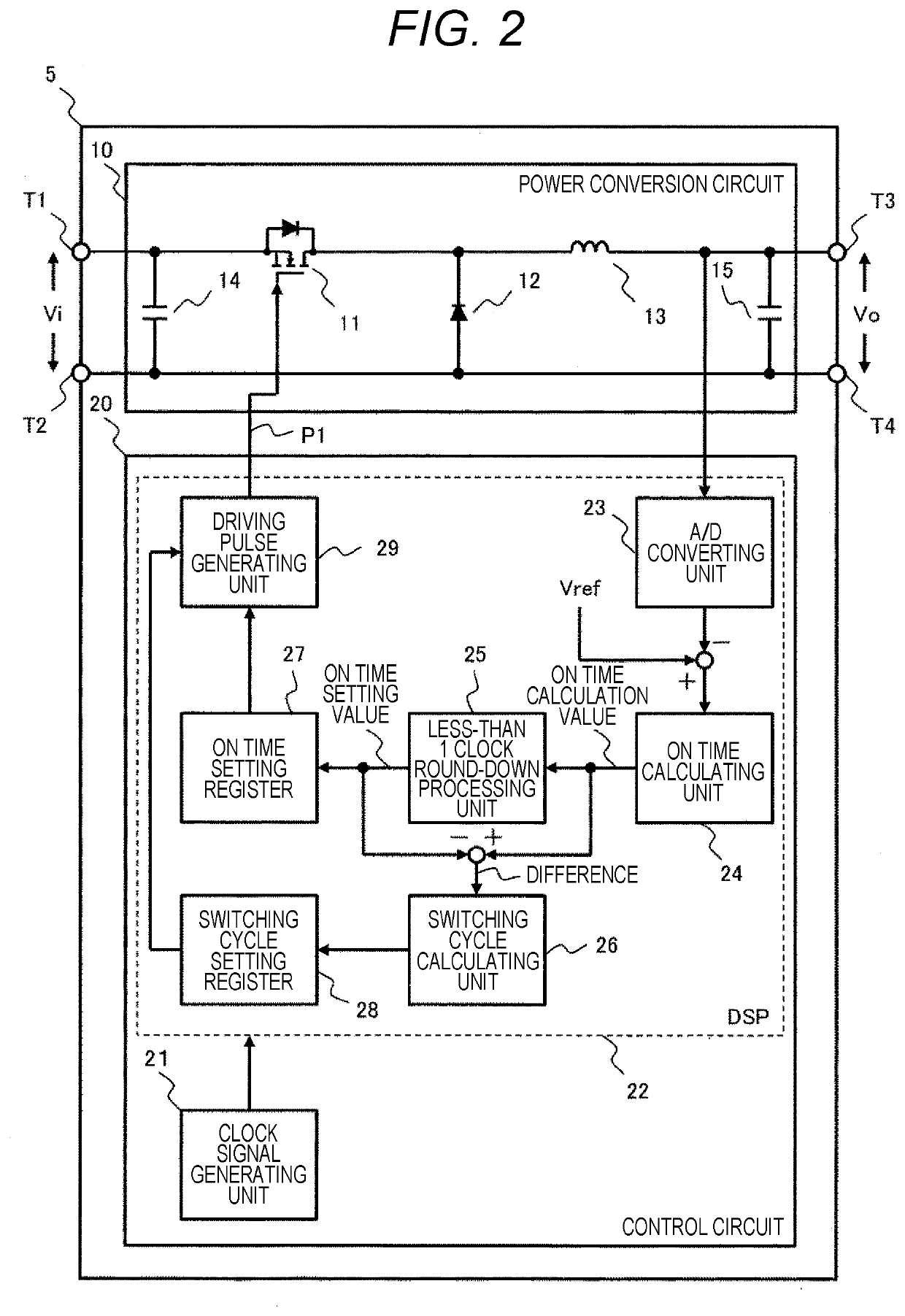
[0025]FIG. 2 is a circuit block diagram of the DC / DC converter 5 according to the first embodiment. The DC / DC converter 5 illustrated in FIG. 2 includes a power conversion circuit 10 and a control circuit 20.

[0026]The power conversion circuit 10 includes a switching element 11, a diode 12, an inductor 13, an input smoothing capacitor 14 and an output smoothing capacitor 15, and converts power by driving the switching element 11 based on a driving pulse P1 outputted by the control circuit 20 by PWM control.

[0027]The power conversion circuit 10 is a so-called buck chopper which bucks an input voltage Vi between input terminals T1 and T2, and outputs an output voltage Vo between output terminals T3 and T...

second embodiment

[0050]The second embodiment of the present invention will be described with reference to FIGS. 5 to 7. The present embodiment improves a voltage control resolution in a case where an insulation type buck converter of a phase shift control system is used as a DC / DC converter 5. A configuration and an operation of the DC / DC converter 5 to which the present embodiment is applied will be described with reference to FIG. 5.

[0051]The DC / DC converter 5 illustrated in FIG. 5 includes a power conversion circuit 30 and a control circuit 40. An ON time of an operation amount of a control circuit 20 in FIG. 2 is only changed to a phase shift amount, and therefore the control circuit 30 will not be described in detail.

[0052]First, a configuration of the power conversion circuit will be described. The power conversion circuit 30 includes a transformer T which includes a primary winding N1, a secondary winding N2 and a secondary winding N3 (N2 coil turn=N3 coil turn), a switching circuit 31 which ...


PUM


Abstract

There is provided a switching power supply device which has a high voltage control resolution. A switching power supply device according to the present invention includes: a power conversion circuit which includes a switching element; and a control circuit unit which outputs a driving pulse to the switching element based on an output voltage command value and an output voltage value of the power conversion circuit, and the control circuit unit changes a switching cycle and outputs a driving pulse based on a difference between a calculation value of an operation amount based on the output voltage command value and the output voltage value, and a setting value of the operation amount.

Description

TECHNICAL FIELD[0001]The present invention relates to a switching power supply device.BACKGROUND ART[0002]In recent years, to meet demands for miniaturization, higher performance and higher functionality of switching power supply devices, a digital control system is widely adopted in place of a conventional analog control system. The digital control system includes an A / D converter which samples a control target voltage value, a digital controller which calculates an operation amount based on the voltage value, a counter which counts up / down in synchronization with a clock signal, and a comparator which compares a count value of the counter and the operation amount, and determines a driving pulse width and a phase of a switching element. For example, according to PWM (Pulse Width Modulation) control, the operation amount is changed to change an ON duty (a time ratio of a logic “H”) of a driving pulse outputted by the comparator, and control a control target voltage. In addition, eac...

Claims


Application Information

Patent Timeline
Patent Type & Authority Applications(United States)
IPC IPC(8): H02M3/157H02M3/158H02M3/335H03K7/08
CPCH03K7/08H02M3/157H02M3/158H02M3/33569H02M3/156H02M1/0025H02M3/33573
Inventor TAKAHASHI, NAOYAKUBO, KENJIONO, TAKUMA
Owner HITACHI ASTEMO LTD
Why Eureka
Try Eureka