System and method for reducing aircraft brake wear

a technology of aircraft brakes and brake pads, which is applied in the direction of braking elements, cleaning processes and apparatuses, cleaning using liquids, etc., can solve the problems of brake wear, reduce the tendency of large particles to break off the surface of the carbon disc, so as to reduce the effective roughness of the carbon surface, and reduce the effect of carbon brake wear

Active Publication Date: 2020-06-18
HYDRO AIRE AEROSPACE CORP
View PDF0 Cites 7 Cited by
  • Summary
  • Abstract
  • Description
  • Claims
  • Application Information

AI Technical Summary

Benefits of technology

[0010]The present invention serves to reduce brake wear and increase brake life by affecting the abrasiveness of the carbon-on-carbon interface during the brake operation. The braking system of the present invention introduces, through capture or injection, a friction adjusting material such as a carbon powder between the carbon brake discs from a period when the brakes are initially applied until the brakes are adequately heated. The friction adjusting material serves to lubricate the mating carbon surfaces during the initial phase of taxiing, minimizing temperature induced frictional wear at the surface layers.
[0011]The use of carbon powder as a friction adjusting material reduces carbon brake wear by providing small particles between the brake discs that act as a buffer between the brake discs. Moreover, when carbon powder (e.g., graphite and graphene) or small particles are used at brake application, such use reduces the effective roughness of the carbon surface and reduces the tendency for large particles to break off of the carbon disc surface during non-optimum temperature contact, thereby reducing brake wear.
[0012]In order to place the powder in the brake stack, the material may be injected from a reservoir adjacent the braking surfaces mounted on a stationary portion of the brake assembly. An injector dispenses the friction adjusting material through insufflation into the brake disc stack, between the rotor discs and the stator discs. The injector may include a mechanical means such as a bellows or other device that receives commands when to insufflate powder into the brake stack. In the case of the bellows, the retraction of a piston could draw up the carbon brake dust from the reservoir and the extension of a piston could dispense friction adjusting material.
[0016]The spent friction adjusting material, such as graphite and graphene, may be captured for reuse such as by electromagnetic collectors that direct the carbon to a retaining vessel. Alternatively, the friction adjusting material may be centripetally or gravitationally collected in reservoirs for use with systems that dispense the friction controlling agent. Commands from the brake pedals and / or the brake control system may be used to initiate the collection / reclamation, or dispensing of the spent friction adjusting material. The collection of the particulate also reduces that amount of particulate matter that is introduced into the runway or the airport environment in general.
[0018]In one aspect of the present invention, adaptive braking (i.e., selecting which brakes to apply) may be used in conjunction with, for instance, application of carbon powder to the carbon brake surfaces to further reduce carbon brake wear. When brakes are applied in response to brake commands that are based on multifactorial conditions, brake wear can be minimized. Such conditions may include, for example, aircraft speed, aircraft deceleration rate, aircraft weight, brake temperature, brake command, braking pressure, taxiway patterns at the airport, brake characteristics by manufacturer, tire pressure, taxi speeds, brake wear, skid conditions and wear rate. With adaptive braking, a plurality of brake characteristics can be used at the same time, allowing for mixing brake manufacturers on an aircraft. Brakes can be automatically applied to maintain taxiway speed limits and optimal brake temperatures. Adaptive braking can be used to balance brake wear, balance brake energy, and provide prognostic data for maintenance. Balancing brake wear involves adjusting braking so that the plurality of carbon brake stacks wear evenly when conditions allow.

Problems solved by technology

Moreover, when carbon powder (e.g., graphite and graphene) or small particles are used at brake application, such use reduces the effective roughness of the carbon surface and reduces the tendency for large particles to break off of the carbon disc surface during non-optimum temperature contact, thereby reducing brake wear.

Method used


Image

  • System and method for reducing aircraft brake wear
  • System and method for reducing aircraft brake wear
  • System and method for reducing aircraft brake wear

Examples


Embodiment Construction

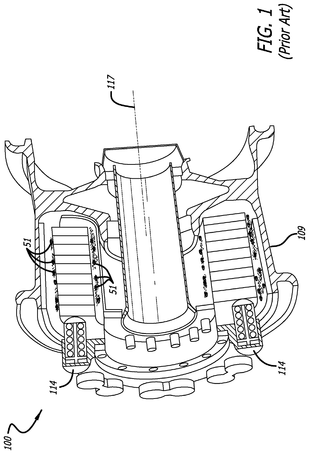
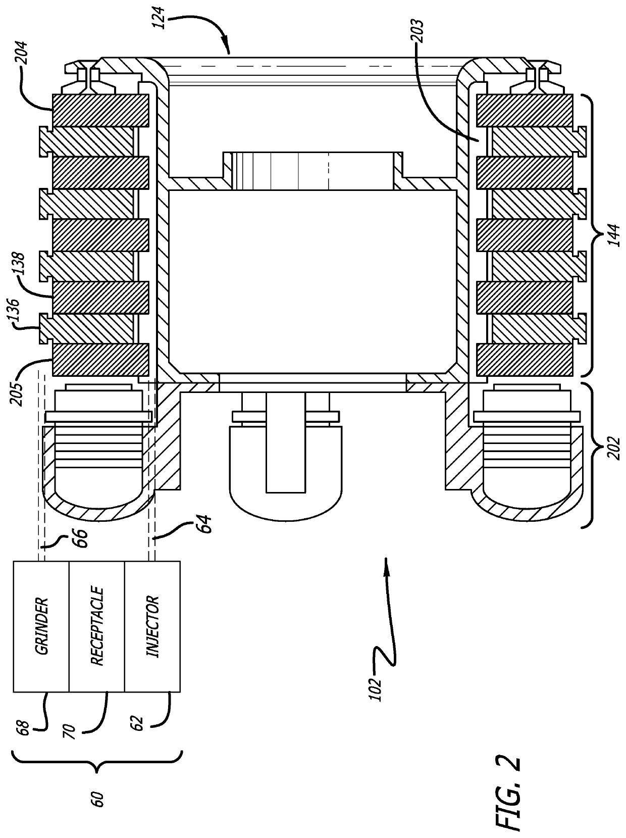
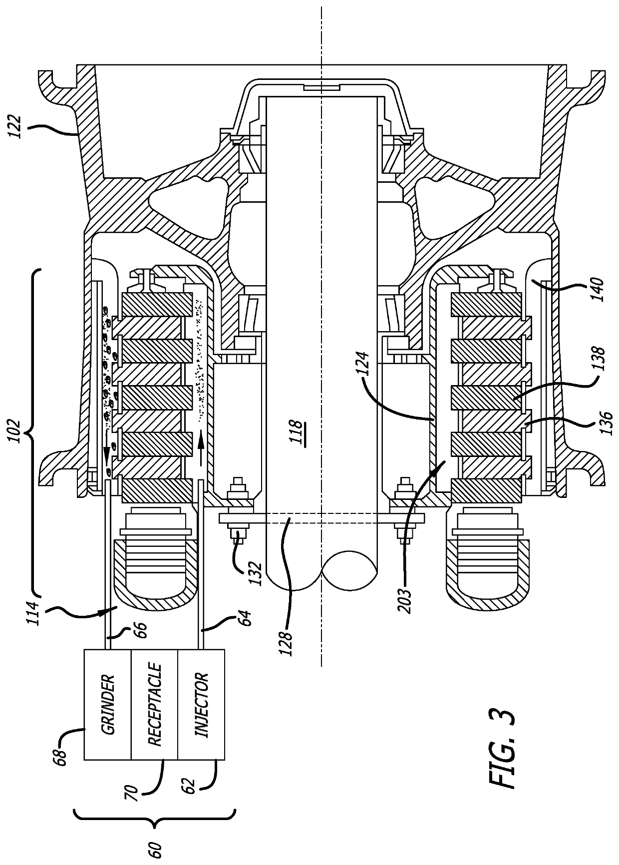
[0025]A prior art aircraft wheel and brake assembly 100 is shown in FIG. 1, where a wheel 109 encompass a plurality of discs of the brake assembly mounted along a centerline 117, that cooperate to arrest the velocity of the aircraft under the influence of an actuator 114. Carbon brakes generally comprise a piston housing 202 including pistons, a torque tube, and a carbon brake stack. The carbon brake stack is made up of several discs (stators) that are keyed to the stationary torque tube, and interleaved discs (rotors) that are keyed to the inside rim of the wheel and rotate with the wheel. The stack is bounded by the piston housing 202 and a pressure plate 205 on one side, and a backing plate 204 on the other side that compress the stators and rotors. During the interaction of the discs, particles 51 that can prematurely wear the discs are dislodged around the inner and outer diameter of the discs. Most of the particles 51 eventually get expelled from the brake assembly 100 and are...


PUM


Abstract

A system and method are provided for continuous monitoring and controlling of aircraft braking that can reduce brake wear and aircraft operating costs through the retention of carbon brake powder from the brakes or addition of carbon powder in a device mounted with respect to the brake disc stack. The use of carbon powder reduces brake wear by providing small particles between the brake discs, acting as a buffer between the brake discs when the brake stack is clamped together. Moreover, when carbon powder or small particles are used at application, such use reduces the roughness of the carbon surface and reduces the number of large particles from braking off the carbon surface, thereby reducing brake wear. Adaptive or selective braking may be used in conjunction with carbon powder to further reduce carbon brake wear.

Description

CROSS-REFERENCES TO RELATED APPLICATIONS[0001]This application claims priority from U.S. Application No. 62 / 780,134, filed Dec. 14, 2018, the content of which is fully incorporated herein by reference.BACKGROUND[0002]This invention generally relates to an apparatus and method for reducing aircraft brake wear, and more particularly to an apparatus and method for reducing carbon brake wear over a variety of braking conditions.[0003]Modern aircraft may be equipped with carbon brakes on each of the main landing gear wheels. Carbon brakes are preferred over their steel counterparts because of their reduced weight and enhanced performance characteristics. Carbon brakes generally comprise a piston housing including pistons, a torque tube, and a carbon brake stack. The carbon brake stack is made up of several discs (stators) that are keyed to the stationary torque tube, and interleaved discs (rotors) that are keyed to the inside rim of the wheel and rotate with the wheel. The stack is bound...

Claims


Application Information

Patent Timeline
Patent Type & Authority Applications(United States)
IPC IPC(8): B64C25/42B60T8/32B60T8/18
CPCB60T8/325B60T8/18B64C25/42F16D65/0037F16D65/0031F16D55/36Y02T50/80F16D65/847F16D65/0043B08B3/08
Inventor HEID, FRANKLIN MICHAELDELORIA, DAVID
Owner HYDRO AIRE AEROSPACE CORP
Why Eureka
Try Eureka