Method and system for neutralizing the effect of vibrations in a rotary-wing aircraft for airborne doppler radar

a technology of airborne doppler radar and rotary wings, which is applied in the direction of reradiation, measurement devices, instruments, etc., can solve the problems of increasing the length of integration time, affecting the operation of airborne radar, and the effect of the movement of the platform aircraft on the operation of the radar, so as to avoid constraining the choice

Active Publication Date: 2020-06-25
THALES SA
View PDF0 Cites 0 Cited by
  • Summary
  • Abstract
  • Description
  • Claims
  • Application Information

AI Technical Summary

Benefits of technology

[0010]A first technical problem resolved by the invention is that of proposing a method for neutralizing the effect of the vibrations of a rotary-wing aircraft for an airborne Doppler radar which avoids the need to use an inertial navigation unit for its implementation and avoids constraining the choice of the areas of installation of the radar antenna(s).

Problems solved by technology

The effect of the movements of the platform aircraft on the operation of an airborne radar is a well-known problem.
In the case of a rotary-wing aircraft, the movements of the rotors create significant vibrations in the overall structure of the platform.
The movements of the radar antenna caused by the vibrations of the platform create parasitic effects in this processing, which increase with the length of the integration time.
This depends on the areas where the radar antennas are installed and on the mechanical coupling between the inertial navigation unit and the radar antennas, and this is a drawback of this method.

Method used


Image

  • Method and system for neutralizing the effect of vibrations in a rotary-wing aircraft for airborne doppler radar
  • Method and system for neutralizing the effect of vibrations in a rotary-wing aircraft for airborne doppler radar
  • Method and system for neutralizing the effect of vibrations in a rotary-wing aircraft for airborne doppler radar

Examples


first embodiment

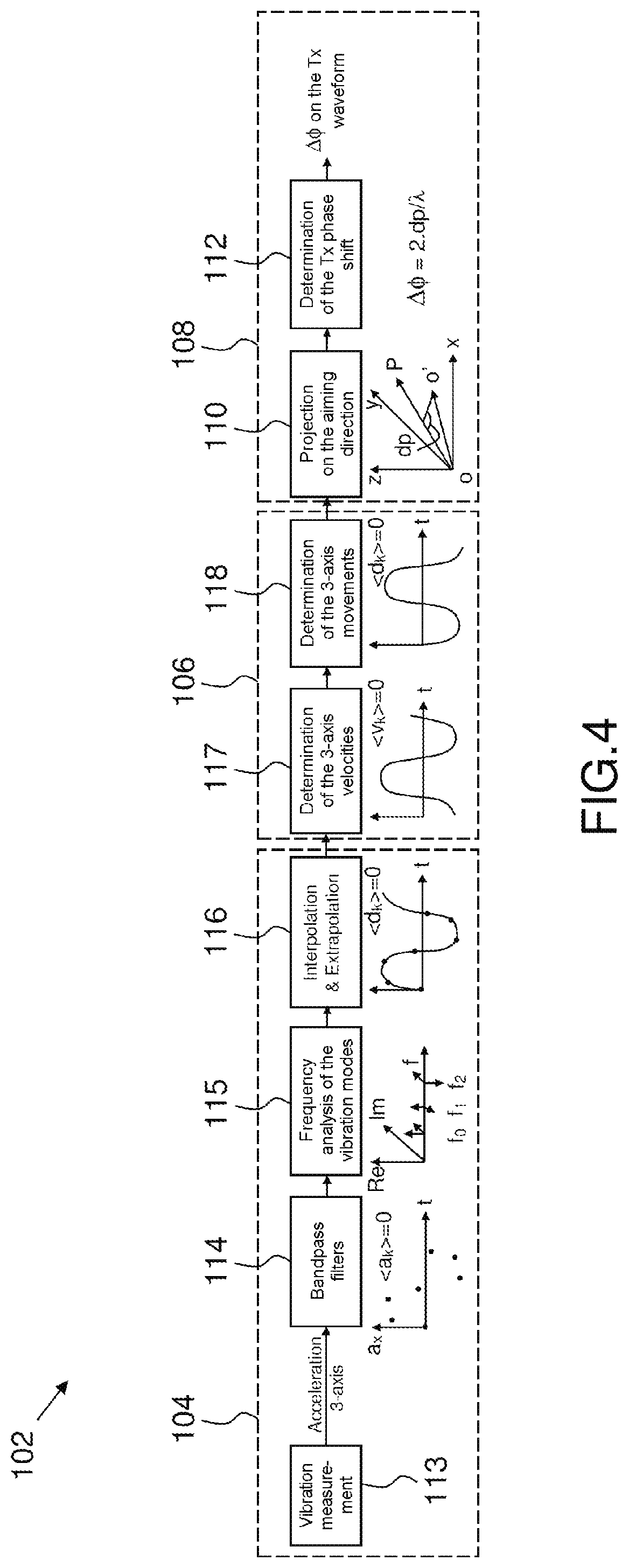
[0064]According to FIGS. 3 and 4 and a first embodiment, the corresponding phase shift Δϕ is then compensated during the generation of the waveform in the transmission chain Tx, with allowance for the outward and return path of the signal, the antenna being considered to be immobile during this outward and return period. Thus, for a given aiming direction {right arrow over (OP)}, the Doppler effect created by the vibrations is neutralized upstream of the signal generation. No further processing is required for receiving the signal.

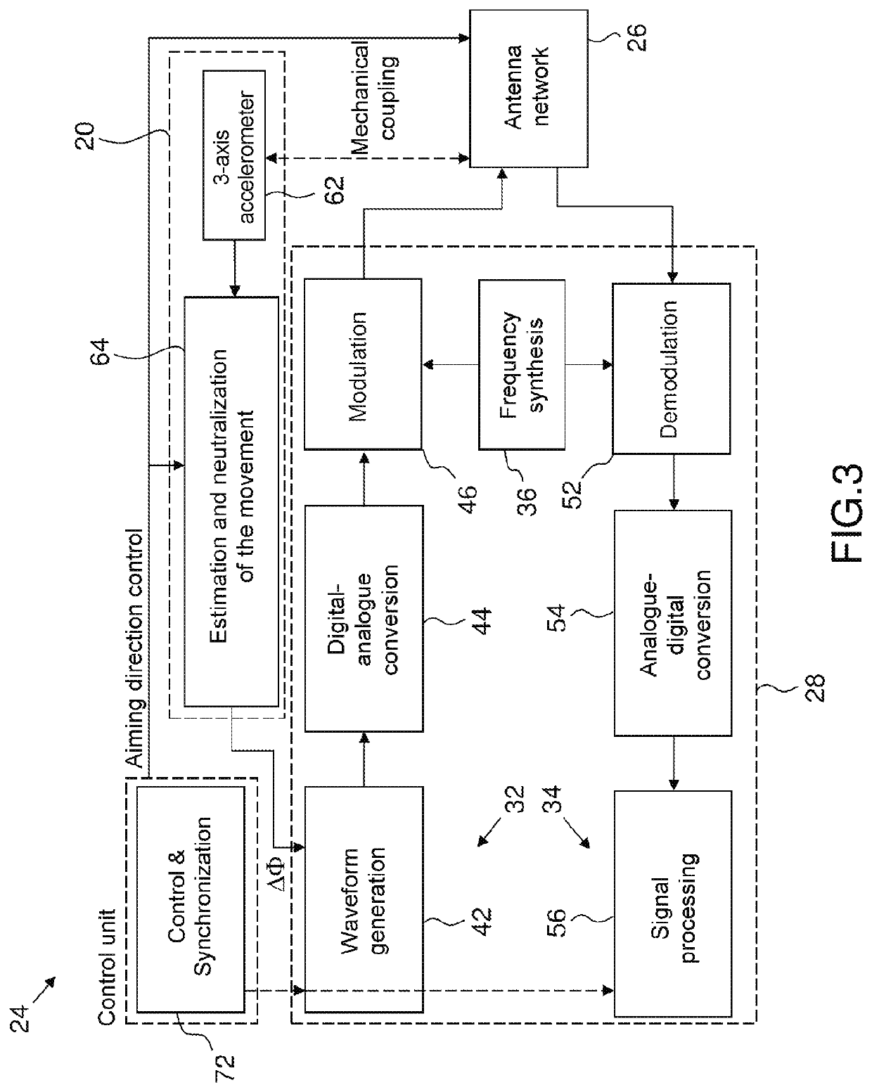
[0065]According to FIG. 3 and a first embodiment, a system for active neutralization 20 of the effect of the vibrations of a rotary-wing aircraft (not shown) for an airborne Doppler radar is integrated in this case into a monostatic Doppler radar 24.

[0066]The monostatic Doppler radar 24 comprises a transmitting-receiving radar antenna 26, which in this case takes the form of an antenna network, having the same phase centre, and comprises a radar transmitte...

second embodiment

[0099]According to FIG. 7 and a second embodiment, a system 220 for actively neutralizing the effect of the vibrations of a rotary-wing aircraft for Doppler radar is integrated into a monostatic Doppler radar 224 by being implemented in the reception chain 234 of the radar 224, and not in the transmission chain as described for the Doppler radar 24 of FIG. 3.

[0100]The active neutralization system 220 has an internal architecture identical to that of the active neutralization system 20 of FIG. 3, in that it comprises the same device for estimating and neutralizing the movement 64 and the same vibration sensor 62.

[0101]The active neutralization system 220 differs from the neutralization system 20 of FIG. 3 in that it comprises an output link 222 of the device for estimating and neutralizing the movement 64, connected to the demodulator 252 of the reception chain 234 of the radar 224.

[0102]The monostatic Doppler radar 224, which incorporates the active neutralization system 220, compri...

third embodiment

[0106]According to FIG. 9 and a third embodiment, a system 320 for actively neutralizing the effect of the vibrations of a rotary-wing aircraft for Doppler radar, formed by two sub-systems 3201 and 3202 connected in series, is integrated into a monostatic Doppler radar 324 by being implemented in the Rx digital radar signal processing module 356 of the reception chain 234 of the radar 224, and not in the demodulator 252 of the reception chain 234 as described for the Doppler radar 224 of FIG. 7.

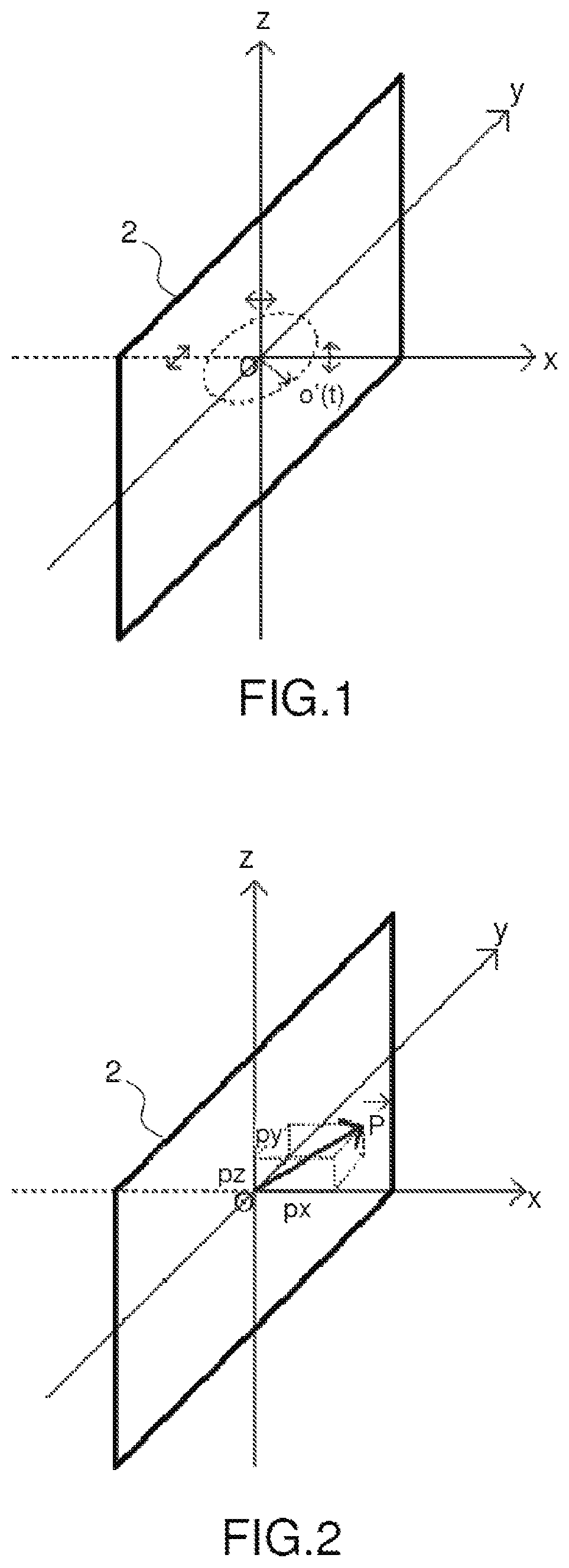
[0107]The active neutralization system 320 can thus be broken down into a first sub-system 3201 for measuring and estimating the components px, py, pz of the expected movement vector {right arrow over (dp)} of the phase centre O of the transmitting-receiving antenna 26 and a second sub-system 3202 for neutralizing N estimated expected movements dp(j) associated with N different aiming directions of the receiving antenna, N being a predetermined whole number.

[0108]The first sub-system 3201 for...


PUM


Abstract

A method for active neutralization of the effect of the vibrations of a rotary-wing aircraft for a monostatic Doppler radar includes a first step of measuring and temporally extrapolating the vibration modes at the transmitting-receiving radar antenna, using a 3-axis vibration sensor, fixed to the antenna and near the phase centre of the antenna; then a second step of estimating the expected movements of the transmitting-receiving antenna or of the first transmitting antenna and the second receiving antenna; then a third step of compensating the expected movements of the transmission radar antenna in the transmission chain or in the reception chain of the radar transmitter, wherein the projection of the movement vector of the phase centre O on an aiming direction is calculated to determine the value of the compensation phase shift to be applied.

Description

CROSS-REFERENCE TO RELATED APPLICATIONS[0001]This application claims priority to foreign French patent application No. FR 1873374, filed on Dec. 20, 2018, the disclosure of which is incorporated by reference in its entirety.FIELD OF THE INVENTION[0002]The present invention relates to a method and system for neutralizing the effect of vibrations in a rotary-wing aircraft for airborne Doppler radar.[0003]The technical field of the invention is that of Doppler processing and the field of application is mainly that of helicopter radars.BACKGROUND[0004]The effect of the movements of the platform aircraft on the operation of an airborne radar is a well-known problem. In particular, these movements have a considerable effect in the field of coherent radar processing, for example the extraction of the Doppler velocity.[0005]In the case of a rotary-wing aircraft, the movements of the rotors create significant vibrations in the overall structure of the platform. The vibration modes of the pla...

Claims


Application Information

Patent Timeline
Patent Type & Authority Applications(United States)
IPC IPC(8): G01S13/58G01S13/60
CPCG01S13/60G01S13/585G01S7/4026G01S13/90G01S13/003G01S7/023
Inventor GARREC, PATRICKCOTTRON, RODOLPHEVEYRAC, YOAN
Owner THALES SA
Why Eureka
Try Eureka