Video display apparatus and video display system

Active Publication Date: 2020-06-25
HITACHI-LG DATA STORAGE
View PDF0 Cites 3 Cited by
  • Summary
  • Abstract
  • Description
  • Claims
  • Application Information

AI Technical Summary

Benefits of technology

[0004]As illustrated in FIG. 17 of US 2003/0165017 A1, the optical device described in US 2003/0165017 A1 includes a beam splitter configured to split a ray, to thereby be able to increase the width of a light flux of light exiting the substrate to enlarge an eye box, which is an area in which the user can see a video even when the user's eyes mov

Problems solved by technology

However, a relationship between an interval between light beams obtained by splitting the light flux by the beam splitter and the diameter of the light flux exhibited before

Method used


Image

  • Video display apparatus and video display system
  • Video display apparatus and video display system
  • Video display apparatus and video display system

Examples


first embodiment

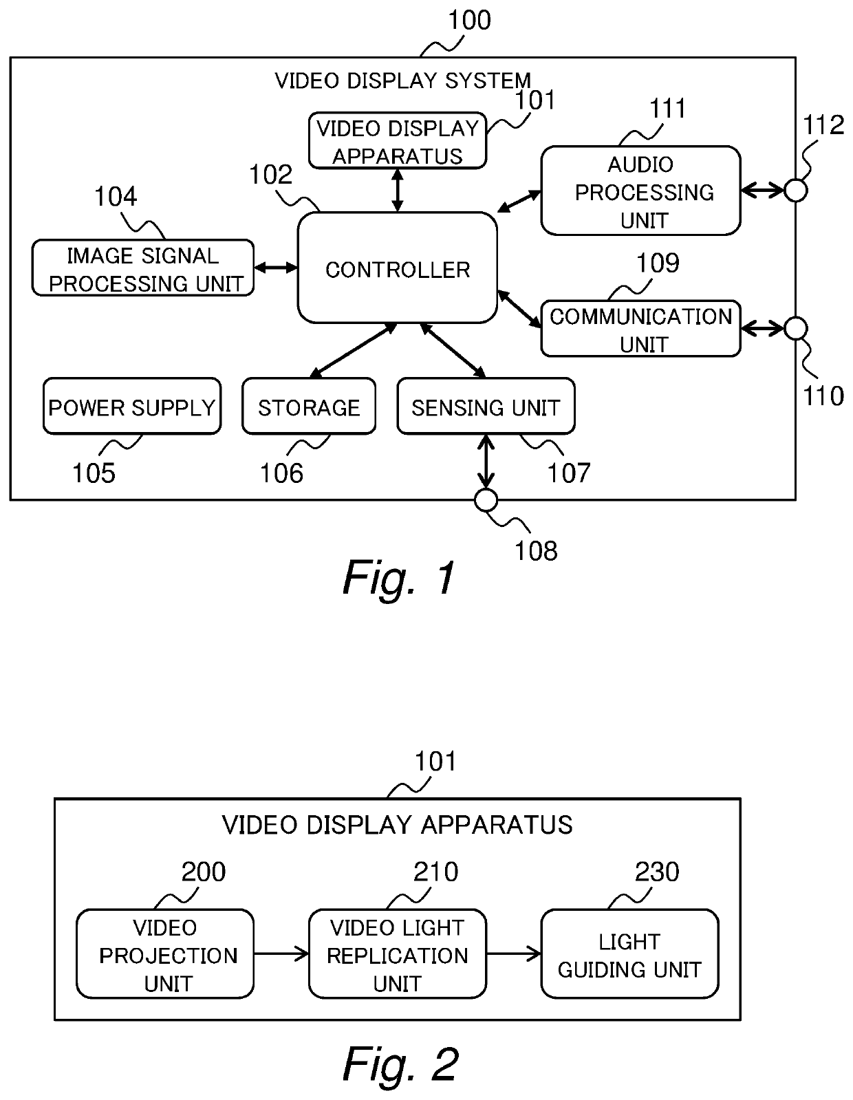
[0038]FIG. 1 is a diagram for illustrating an example of functional blocks of a video display system 100 according to a first embodiment of this invention.

[0039]The video display system 100 is a system having a function of displaying a video, for example, a head-mounted display or a head-up display. The video display system 100 includes a video display apparatus 101, a controller 102, an image signal processing module 104, a power supply unit 105, a storage medium 106, a sensing unit 107, a sensor input / output unit 108, a communication unit 109, a communication input / output unit 110, an audio processing unit 111, and an audio input / output unit 112.

[0040]The video display apparatus 101 is an apparatus configured to generate a video and display the video to a user of the video display system 100, which is described later in detail.

[0041]The controller 102 centrally controls the entire video display system 100. The controller 102 has the function implemented by, for example, a central ...

second embodiment

[0120]In a second embodiment of this invention, the light guiding unit 230 includes a light guide plate 802 and an angle-of-view correction unit (triangular prism 400). In the second embodiment, a description is mainly given of differences from the above-mentioned embodiment, and the same components as those of the above-mentioned embodiment are denoted by the same reference symbols, and their descriptions are omitted below.

[0121]FIG. 14 is a diagram for illustrating a configuration example of the video display apparatus 101 according to the second embodiment, in which a view from the front of the light guide plate 802 is illustrated on the upper side and a view from the top side of the light guide plate 802 is illustrated on the lower side. The light guiding unit 230 includes the light guide plate 802 and the angle-of-view correction unit. The angle-of-view correction unit includes the triangular prism 400. FIG. 15A, FIG. 15B, and FIG. 15C are a front view, a plan view, and a side ...

third embodiment

[0127]In a third embodiment of this invention, the video light replication unit 210 includes a pupil expanding prism 301 in place of the pupil expanding prism 300. The pupil expanding prism 301 in the third embodiment is configured so that at least a part of the entering video light enters the second partially reflecting surface without entering the first partially reflecting surface. In the third embodiment, the same components as those of the above-mentioned embodiments are denoted by the same reference symbols, and their descriptions are omitted below.

[0128]FIG. 16 shows a front view, a plan view, and a side view, respectively, of the pupil expanding prism 301. The pupil expanding prism 301 includes the first partially reflecting surface in its inside. The first partially reflecting surface reflects at least a part of the light, and transmits at least a part of the light.

[0129]The video light emitted from the video projection unit 200 enters the pupil expanding prism 301 through ...


PUM


Abstract

To provide a wide eye box and are capable of displaying a video having uniform luminance, it is provided a video display apparatus comprising: a video projection unit configured to project video light; a video light replication unit configured to replicate the video light; and a light guiding unit configured to transmit the video light through an inside of the light guiding unit, wherein the video light replication unit is configured to transmit the video light emitted from the video projection unit to the light guiding unit, wherein the light guiding unit is configured to transmit the video light that has entered through the inside to output the video light, and wherein the video light replication unit is configured to replicate the video light that has entered the video light replication unit so that a luminance distribution of the video light output from the light guiding unit is uniform.

Description

CLAIM OF PRIORITY[0001]The present application claims priority from Japanese patent application JP 2018-240321 filed on Dec. 21, 2018, the content of which is hereby incorporated by reference into this application.BACKGROUND OF THE INVENTION[0002]This invention relates to a video display apparatus and a video display system.[0003]There is known a head-mounted display or other such video display system configured to present a video generated by a video generation apparatus to a user. For example, in US 2003 / 0165017 A1, there is disclosed an optical device including a light-transmitting substrate, optical means for coupling light into the substrate by total internal reflection, and a plurality of partially reflecting surfaces carried by the substrate, characterized in that the partially reflecting surfaces are parallel to each other and are not parallel to any of the edges of the substrate (see claim 1).SUMMARY OF THE INVENTION[0004]As illustrated in FIG. 17 of US 2003 / 0165017 A1, the...

Claims


Application Information

Patent Timeline
IPC IPC(8): G02B27/01F21V8/00G02B27/09G02B27/00G02B27/14
CPCG02B2027/0123G02B27/0081G02B27/145G02B2027/0178G02B27/0927G02B2027/0112G02B6/0031G02B2027/014G02B27/0172H04N9/3141H04N13/344H04N13/324G02B6/34
Inventor UKAI, RYUJINAKAMURA, TOSHITERUKUNO, TAKUMAOUCHI, SATOSHI
Owner HITACHI-LG DATA STORAGE
Why Eureka
Try Eureka