
Electroluminescence display apparatus

Active Publication Date: 2020-06-25
LG DISPLAY CO LTD
View PDF0 Cites 4 Cited by
  • Summary
  • Abstract
  • Description
  • Claims
  • Application Information

AI Technical Summary

Benefits of technology

This patent describes a technology for improving the manufacturing of electroluminescence display devices. By using two planarizing layers, the technology provides additional space for disposing wiring lines between the layers and reduces the distance between them, lowering wiring resistance. Additionally, a new structure is used to minimize gas outgassed from the planarizing layer, reducing the likelihood of pixel shrinkage and improving the reliability of the display. The technology also utilizes a planarization pattern in the non-display area to further reduce gas outgassing. Overall, the technology provides improved manufacturing efficiency and reliability for electroluminescence display devices.

Problems solved by technology

For example, in accordance with the demand for higher resolution, a larger number of wiring lines may need to be disposed in a limited space, therefore creating a problem that an interval between wiring lines may be insufficient.
Furthermore, when a width of the wiring line is reduced to dispose the larger number of wiring lines, the resistance of the wiring lines may be undesirably increased.
When the remaining gasses are outgassed from the planarizing layer, and the gases outgassed from the planarizing layer are moved to a cathode of the light emitting element, the cathode may be oxidized, which may result in a pixel shrinkage defect.

Method used


Image

  • Electroluminescence display apparatus
  • Electroluminescence display apparatus
  • Electroluminescence display apparatus

Examples


Embodiment Construction

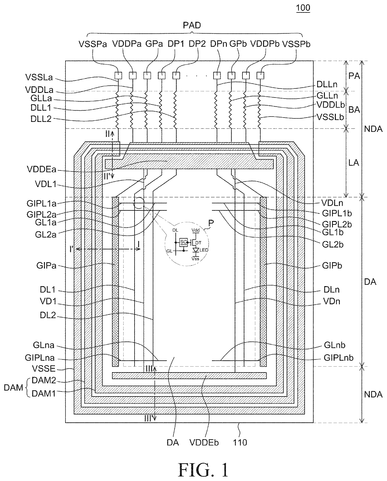
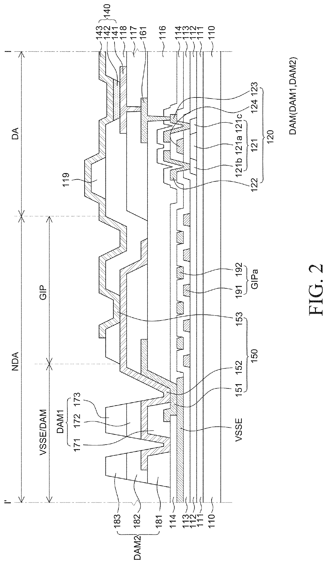
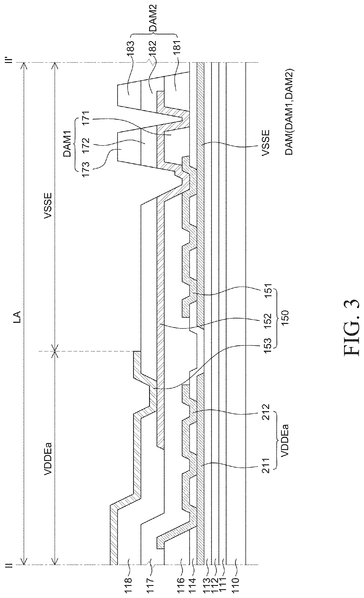
[0024]Reference will now be made in detail to the example embodiments of the present disclosure, examples of which are illustrated in the accompanying drawings. Wherever possible, the same reference numbers will be used throughout the drawings to refer to the same or like parts. Advantages and features of the present disclosure, and implementation methods thereof will be clarified through following embodiments described with reference to the accompanying drawings. The present disclosure may, however, be embodied in different forms and should not be construed as limited to the embodiments set forth herein. Rather, these embodiments are provided so that this disclosure will be thorough and complete, and will fully convey the scope of the present disclosure to those skilled in the art. Further, the present disclosure is only defined by scopes of claims.

[0025]The shapes, sizes, ratios, angles, numbers, and the like illustrated in the accompanying drawings for describing the exemplary em...


PUM


Abstract

An electroluminescence display apparatus includes a substrate including a display area and a non-display area. The non-display area includes a bending area and a link area. A first power supply electrode is in the link area. A second power supply electrode is in the non-display area. The second power supply electrode surrounds at least three sides of the display area, and both ends of the second power supply electrode in the link area. A protective layer covers the first power supply electrode and the second power supply electrode in the link area. A first planarizing layer covers one side of the first power supply electrode; and a second planarizing layer is on a contact hole of the protective layer that exposes the first power supply electrode and the second power supply electrode. The first planarizing layer is not on the contact hole.

Description

CROSS-REFERENCE TO RELATED APPLICATIONS[0001]This application claims the priority of Korean Patent Application No. 10-2018-0165883 filed on Dec. 20, 2018, in the Korean Intellectual Property Office, the disclosure of which is incorporated herein by reference in its entirety.BACKGROUNDTechnical Field[0002]The present disclosure relates to an electroluminescence display apparatus, and more particularly, to an electroluminescence display apparatus that reduces gases outgassed from a planarizing layer to improve reliability.Description of the Related Art[0003]An electroluminescence display apparatus may be a self-emitting display apparatus in which a separate light source is not necessary, unlike a liquid crystal display apparatus. Therefore, the electroluminescence display apparatus may be manufactured to be thin and lightweight. Further, because the electroluminescence display apparatus may be driven at a low voltage, it may be advantageous in terms of power consumption. Furthermore, ...

Claims


Application Information

Patent Timeline
IPC IPC(8): H01L51/52H01L27/12H01L27/32
CPCH01L51/5203H01L27/3297H01L27/1218H01L27/1244H10K59/124H10K59/131H10K59/805H10K59/123H10K59/1213H10K59/122H10K59/8051H10K59/87H10K50/805
Inventor UM, HYUNCHULPARK, JONGCHANLEE, TAEWON
Owner LG DISPLAY CO LTD
Learn More