Component produced by additive manufacturing

a technology of additive manufacturing and components, applied in the manufacture of sparking plugs, sparking plugs, manufacturing tools, etc., can solve the problems of kerf loss, material loss, complex and expensive processes, etc., and achieve the effect of avoiding additional time-consuming and loss-generating manufacturing processes for the preparation of sectioned wire and its subsequent attachment to a substra

Active Publication Date: 2020-07-02
JOHNSON MATTHEY PLC
View PDF0 Cites 7 Cited by
  • Summary
  • Abstract
  • Description
  • Claims
  • Application Information

AI Technical Summary

Benefits of technology

[0019]The inventors have found that an additive manufacturing method for the manufacture of ignition device components, such as electrodes for ignition devices, offers a very efficient means to produce the components with minimal wasted material. Additional time-consuming and loss-generating manufacturing processes for the preparation of sectioned wire and its subsequent attachment to a substrate are avoided. Moreover, the geometry of the deposited attachment is entirely customisable to suit the particular application, and a strong bond is formed between the substrate and the attachment.

Problems solved by technology

However, the processes are complex and expensive due to the need to prepare the metal wires in an upstream process, section them and perform the necessary welding steps, either to laser-weld each wire section onto a substrate to form the electrode tip or to friction weld the two wires.
Cutting of wire results in kerf loss (the inevitable loss of material when a cutting tool passes through a wire during sectioning).
If a shaped electrode tip (such as a tapered tip) is desired, the end of the slug must be shaped by machining, with inevitable further material loss.
Existing processes also lack flexibility because a specific length of sectioned wire must be used in order to provide the desired corresponding length of electrode tip.
As a result, it may be necessary to prepare and make available a wide variety of lengths of sectioned wire in a preliminary stage of the process, which is complex.
The handling of slugs and other small portions of wire is difficult and results in further losses.

Method used


Image

  • Component produced by additive manufacturing
  • Component produced by additive manufacturing
  • Component produced by additive manufacturing

Examples


sixth embodiment

[0080]In the invention, the substrate may be an ignition device component, for example an ignition device electrode, for example a spark plug electrode. In other embodiments, the substrate may be any other suitable metal or alloy substrate, for example a lead-out wire of a sensor.

[0081]Additive Manufacturing Process

[0082]The process according to the invention uses methods of additive manufacturing (AM). AM is a technique whereby 2-dimensional layers of material are sequentially laid down and fused or bound together to form 3-dimensianal solid objects. The technique has been developed for the fabrication of plastic, metal and ceramic components for use in aerospace and medical applications.

[0083]The inventors have discovered that AM also offers the possibility to produce ignition device components in an economical way while preserving desirable properties.

[0084]The inventors have also discovered that AM offers the possibility to produce noble metal-containing components in an economi...

embodiment 4

[0142]An alternative embodiment 4 is shown in FIG. 4. The bore 32 of FIG. 3 is replaced with a recess 41 within a modified build plate 41. All aspects of this embodiment are identical to that shown in FIG. 3, except that the recess 41 does not extend through the entire thickness of the build plate 41. Like the embodiment shown in FIG. 3, the position of the substrate 2 is controlled by the presence of an annular ridge 48a, 48b. The axial position of the annular ridge 48a, 48b within the bore 42 is designed such that the upper surface 45 of the substrate 2 is substantially coplanar with the upper surface 46 of the build plate 41.

embodiment 5

[0143]An alternative embodiment 5 is shown in FIG. 5. The bore 32 of FIG. 3 is replaced with a recess 52 within a modified build plate 51, and the bottom of the substrate 2 rests on the floor 52a of the recess 52. The depth of the recess 52 is designed such that the upper surface 55 of the substrate 2 is substantially coplanar with the upper surface 56 of the build plate 51.

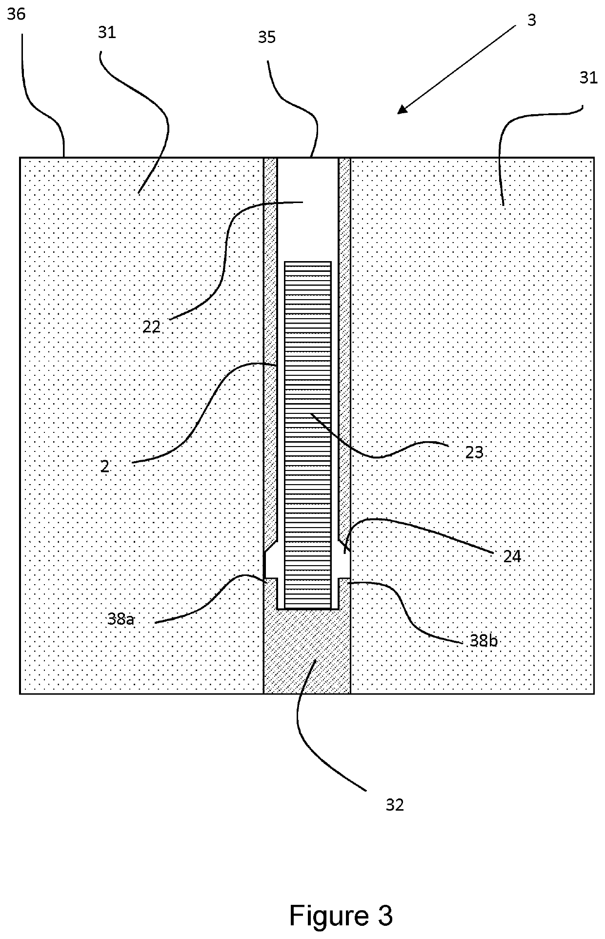
[0144]The upper surface 35 of the substrate, which has a circular shape, is coplanar with the upper surface 36, 46, 56 of the build plate. The arrangements shown in FIGS. 3-5 facilitates the deposit of material onto the substrate by AM, and the subsequent formation of an attachment fixed to the upper surface 35 of the substrate 2.

[0145]FIG. 6 shows a spark plug electrode 6 according to the invention. A platinum-group metal attachment 61 has been deposited in stages by a powder bed fusion AM process onto the upper surface of the substrate 2. The attachment 61 is fused to the substrate 2. The component 6 is still p...


PUM

PropertyMeasurementUnit
particle sizeaaaaaaaaaa
lengthaaaaaaaaaa
particle sizeaaaaaaaaaa

Abstract

The present invention relates generally to components prepared by additive manufacturing (AM) methods, along with methods of preparing such components by AM. More especially, there is provided a process for the production of a component of an ignition device using an AM method by forming a layer of metal or alloy on a surface of a metal or alloy substrate; fusing the layer to the substrate; and repeating the addition of such layers upon one another to form a deposited metal or alloy attachment on the substrate.

Description

TECHNICAL FIELD[0001]The present invention relates generally to components prepared by additive manufacturing (AM) methods, along with methods of preparing such components by AM.BACKGROUND ART[0002]It is often necessary to attach a noble metal or noble metal-containing alloy to another metal or alloy to form an assembly. The other metal or alloy may also be noble metal-based or may be another type of metal or alloy. The noble metals consist of ruthenium (Ru), rhodium (Rh), palladium (Pd), silver (Ag), osmium (Os), iridium (Ir), platinum (Pt) and gold (Au).[0003]The joining of a metal or alloy to another metal or alloy to form an assembly is also necessary when manufacturing ignition system devices, such as spark plugs. Such devices include components such as a central electrode which is usually connected to the ignition system, and a ground or side electrode which is grounded by connection to the metal shell of the ignition device. The tip of the ignition device component (for examp...

Claims


Application Information

Patent Timeline
Patent Type & Authority Applications(United States)
IPC IPC(8): B33Y10/00B22F3/105
CPCH01T13/39H01T21/02B22F3/1055B33Y30/00B33Y80/00B22F2003/1057B33Y10/00B23K26/342B22F5/008B22F7/08B32B15/018C22C1/0466C22C5/04H01T13/20B33Y70/00B32B15/01C22C5/00B33Y50/02C22C19/05C22C9/00B33Y40/20B22F2999/00B22F10/64B22F10/66B22F10/25B22F10/28B22F12/30B22F12/90B22F10/73B22F10/30B22F3/24B22F3/15B22F2003/247B22F10/368B25F5/008B33Y70/10B22F10/00
Inventor COUPLAND, DUNCAN ROYEDGAR, JONATHANTO, NELSON
Owner JOHNSON MATTHEY PLC
Why Eureka
Try Eureka